My initial plan was to create a simulation of a frosted glass to hide and reveal a background image but I found out through testing that adjusting the opacity using an analog switch was pointless– opacity acted like an on/off switch where if the potentiometer went to 1024, opacity would be 1, else, it would go straight to 0.
I think having a lot of CSS linked to the div on the page also burnt the pot out a bit and started to smell like burnt plastic.
I resorted to creating a stripe pattern using I’s to create a hack “animation” produced by changing the letter spacing. I can imagine making interactive grids and zigzag patterns with it using a variety of keyboard characters.
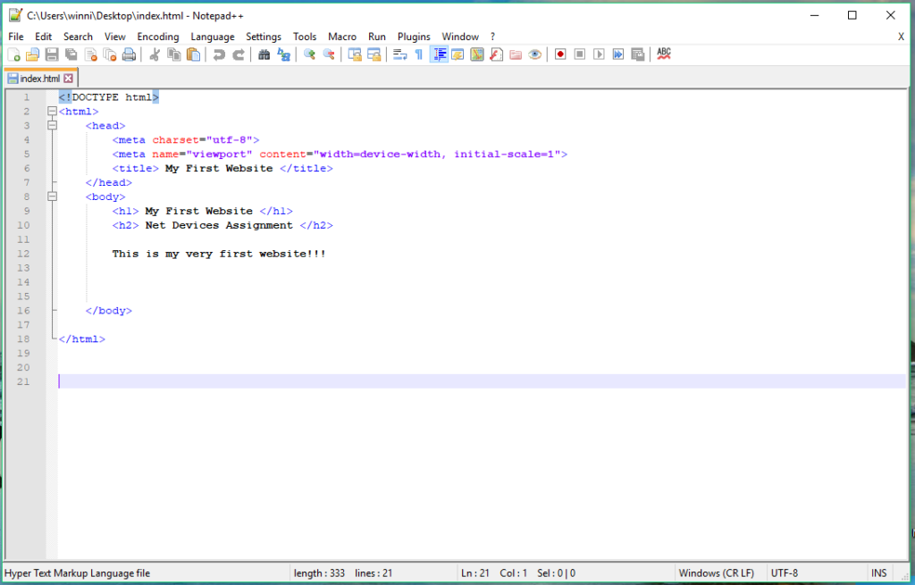
I tried to make a webpage that would count how many times I pressed the switch. I am not good at coding, so it took me some time and I still didn’t get how I should code anything or where I should start. For now I’ve started learning some html so I created the most basic website ever. It basically just displays whatever I typed there in the page.
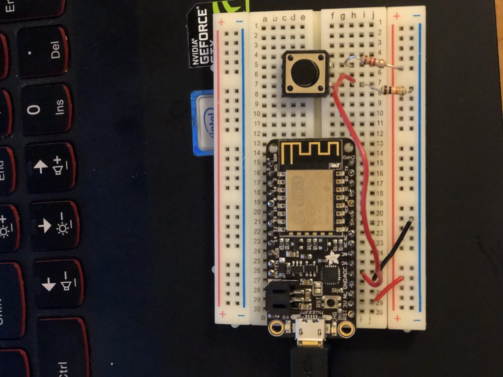
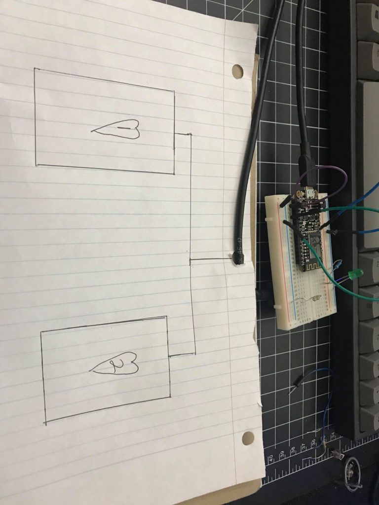
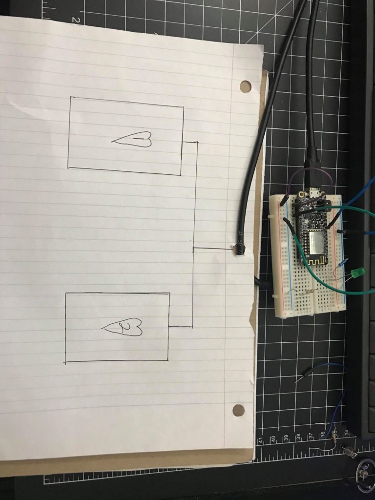
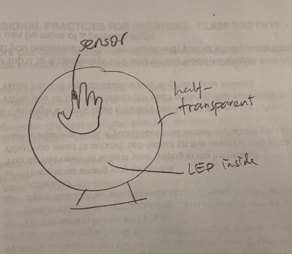
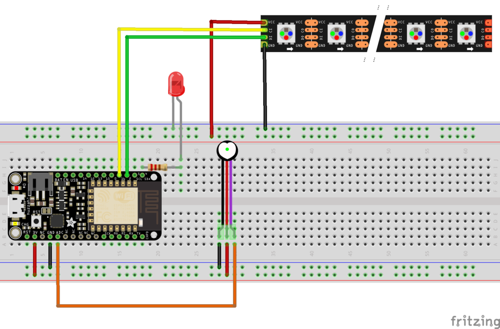
I’ve also finally got a working usb, so I was able to use the switch code we did like 2 weeks ago. but for the sensor server hw I would like my board to be set up like this.
For this homework I decided to change the margins on the p elements on the page. If you compress the viewport size, the text will jump around when the margins are increased, and it kind of seems poetic.
Originally, I imagined I would try and change the color of different elements on the page, but I couldn’t figure out how I needed to adapt the syntax of the html to be correct. I thought about using hex values instead of RGB to change the color, but thought I would have needed javascript to convert it. I probably could have done it in the Arduino language, but it still isn’t clear to me what I can and can’t do.
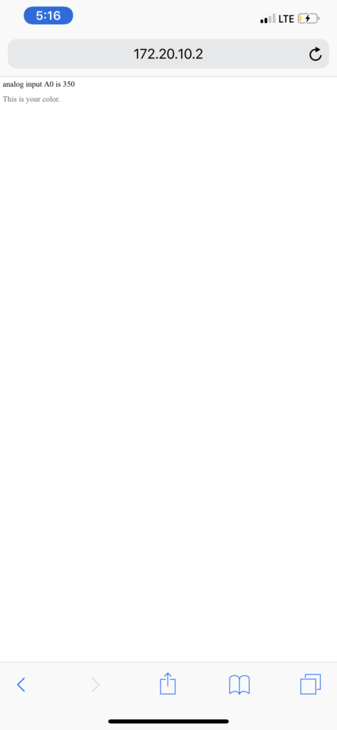
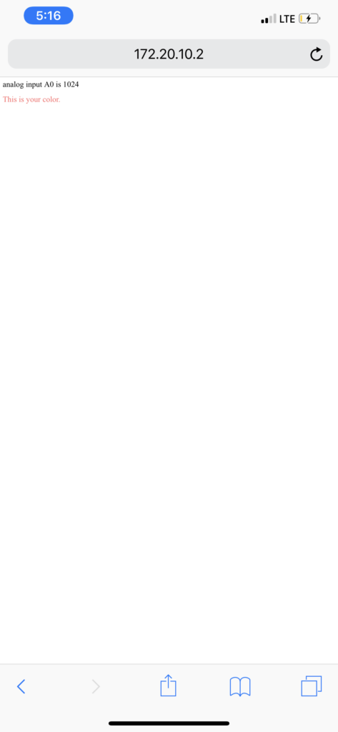
I decided to use the photocell to control the background color of the HTML. I first tried on my phone’s hotspot since the linksys network is not stable at all. I changed the HTML code so the color of the text changed based on the data received from the photocell. After that I tried on the computer and it also works!
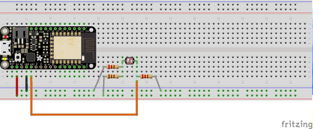
I decided to use a photocell to change different HTML/CSS elements within a webpage. I used the photocell calibration code and added that into the serving data code. The sensor reads values from 0 to 1023, which I mapped to 0 to 255. I modified the HTML and CSS to display 4 gray dots. When the sensor value is above 50, the first dot turns yellow. When it’s above 100, the first and second dots turn yellow, and so on (above 150, 3rd dot; above 225, fourth dot). Basically, it’s a “progress bar” that’s controlled by the amount of light the photocell is detecting.
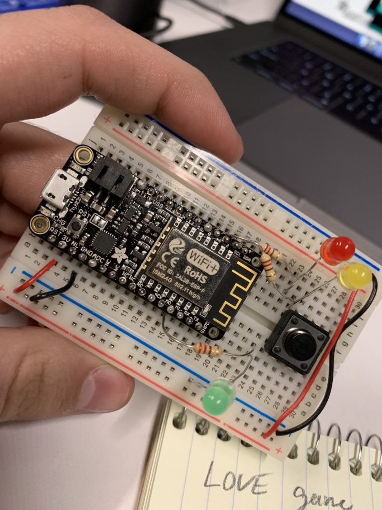
For this assignment I wanted to create a theoretical love machine that was attached to the breadboard. The reason I wanted to make it theoretical is due to the fact that “love” cannot be quantified. But in this “machine” I wanted to create two theoretical switches that could analyze someone’s personalities and match them with each other. And if the two personalities were compatible the LED on the breadboard would light up, signify that there is a sign of “love”
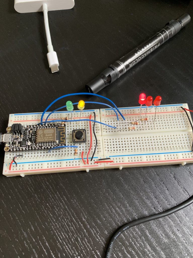
For my love test machine I decided to go with more of a classic interface. Those old machines usually take an input and don’t tell you how you did until the whole game is finished. My idea was to take a button, you press it once to start the game, once the game is started then you start tapping the button furiously as possible to see how many times you can get it to go.
With the readings from last week, I understand that you have to make it clear to the person what they’re doing and where they’re at in the game. They also need a feedback mechanism so they know what’s going on. I used the lights on the left hand side of the board for that purpose. Yellow for when the game is about to start, Green for when the user should tapping as hard as possible, and the three red leds on the right hand side of the board indicate the results and how you did.
Because I was at first struggling with understanding, I started with writing the code for the leds, in order to sequence them in the way I wanted them to. Once I was able to do that then I added in the switch and once I turned the switch into an on and off sequence that’s when it really started to come together. I then organized the components onto another side of the board in order to make sure that it was understandable and doable.
The one issue I have is in the middle when you’re tapping the button delay doesn’t work but I was wondering how I should go about letting the person tap as many times as possible before going onto the next step for like 5 seconds.
*my phone images can’t be uploaded because of HEIC
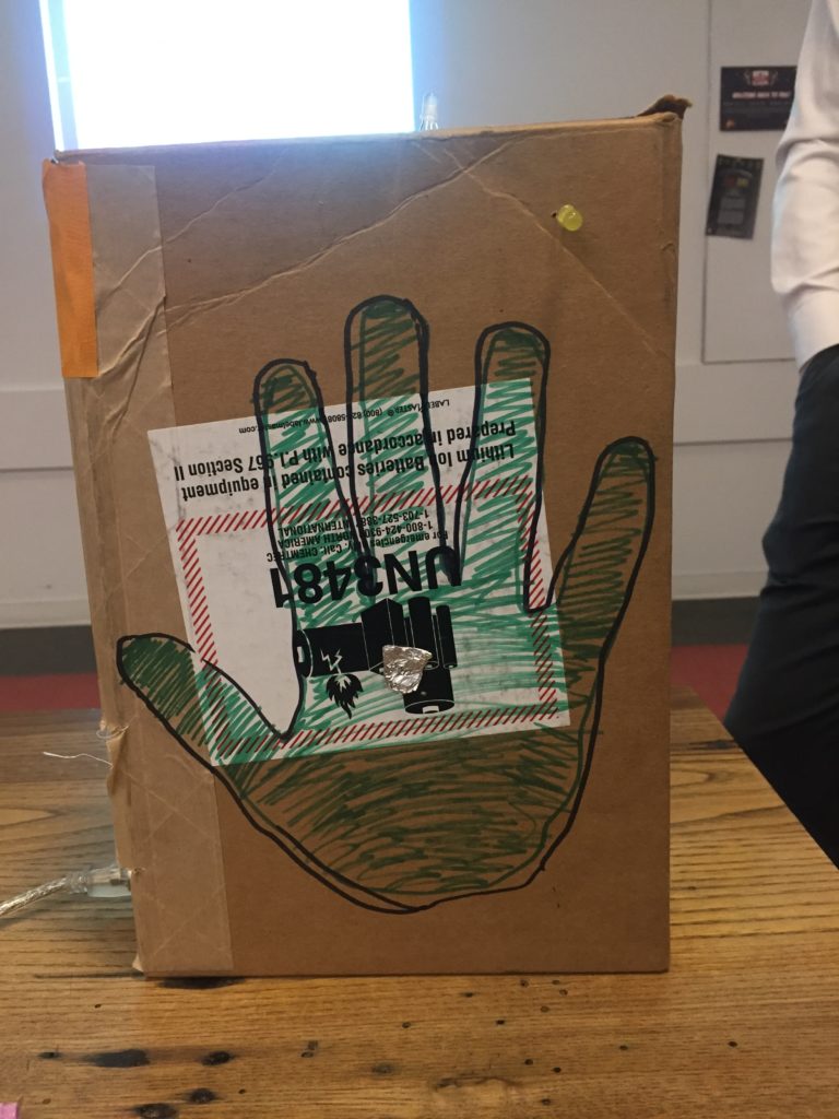
I felt inspired by hands after our hand free switches and decided to make a love machine that required the two potential lovers connect with their hands. I had trouble thinking of way to activate a switch upon their hands connecting so I instead used capacitive sensing to measure when the two people at placed their hand on the machine. Also in order to give the users some signifiers I added a hand-print outline to both sides and led’s that light when each individual hand is sensed.
Materials:
cardboard box (17 cm x 25 cm x 8 cm)
Arduino Uno
2 single-color LEDs
1 RGB LED
resistors (2 x 100K ohm, 5 x 220 ohm)
tin foil
wires
breadboard
Process:
I started with getting the capacitive sensing to work. Essentially capacitive sensing allows us to read whether or not physical contact has been made to skin. It can even sense through other objects if a large enough resistor is used. I used the Arduino CapacitiveSensing library. This is the circuit diagram provided in the library’s documentation:
Capacitive Sensing Circuit
Essentially two digital pins are needed to use capacitive sensing, but one send pin can be used for multiple receive pins. Also the resistor needs to be at least 10k ohms but ideally between 100K ohms and 50M ohms. The larger the resistance the more sensitive the sensing is. I also linked two LEDs to capacitive sensor to give a visual indication if they were being sensed. Sometimes one needs to make firm contact in order for the signal to be picked up.
The next thing I needed to wire up is the RGB led. It is pretty easy to do, just need three pins to control each of the Red, Green, and Blue LEDs as well as resistors between the anode and digital pin. And one final pin that goes to ground. Here is the circuit diagram for that:
RGB LED wiring
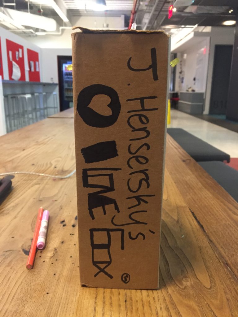
The final thing was putting all the components into the box. I poked holes for all the LED wires and just stuck wires out to connect to the palm of each hand. I designed it so that when the two users put their hands up it seems like they are putting their hands up against each others. I also made both hand prints right hands so that it was clear the machine is supposed to be used with two people instead of just one.
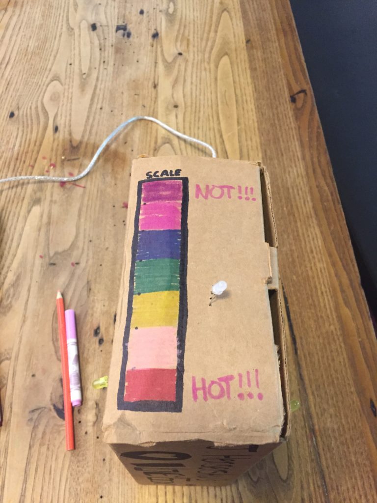
The LED stops on one of the 7 colors of the rainbow which indicates how good they would be together. Red being the best, violet the worst. I made a color coded scale on the top next to the RGB led in order to illustrate this.
The box is relatively self contained so there aren’t too many affordances here for the user. The only real option is place your hand where the hand print is. Once you place your hand an LED will light up giving indication that something had been activated. If they take their hand away the LED deactivates and its clear what caused it. When both hands are put up both LED’s start blinking rapidly and then stop at which point the RGB led cycles through colors until it finally picks one and blinks that color. A relatively simple yet self-explanatory device.
// Choose the colours to increment and decrement.
for (int decColour = 0; decColour < 3; decColour += 1) {
int incColour = decColour == 2 ? 0 : decColour + 1;
// cross-fade the two colours.
for(int i = 0; i < 255; i += 1) {
  rgbColour[decColour] -= 1;
  rgbColour[incColour] += 1;

  setColor(rgbColour[0], rgbColour[1], rgbColour[2]);
  delay(5);
}
}
}
void setup()
{
cs_2_3.set_CS_AutocaL_Millis(0xFFFFFFFF); // turn off autocalibrate on channel 1 – just as an example
Serial.begin(9600);
pinMode(led1, OUTPUT);
pinMode(led2, OUTPUT);
pinMode(rPin, OUTPUT);
pinMode(gPin, OUTPUT);
pinMode(bPin, OUTPUT);
}
void loop()
{
long start = millis();
long total1 = cs_2_3.capacitiveSensor(30);
long total2 = cs_2_4.capacitiveSensor(30);
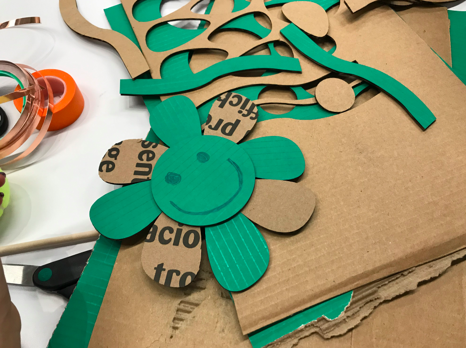
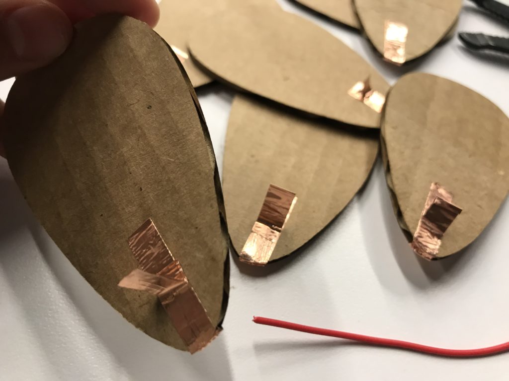
Che-Yu and I came up with an idea of using the fortune-telling game “He loves me, he loves me not” or “She loves me, she loves me not” to see whether or not you are compatible with your soulmate. In this game, one person will speak the phrases “He (or she) loves me,” and “He (or she) loves me not,” while picking one petal off a flower for each phrase. The phrase for the last picked petal represents the truth between the object of their affection returns that affection or not.
As for our love machine, the player will do the same as the game. While the seven petals are picked off, the color of RGB LED light will change from red to green to blue. In order to solve the issue that there will always be only seven petals and the player might have already known the outcome without picking off the petals, we set a random value for the beginning status. If the LED lights up in the end, it means you are compatible with your affection. If not, you could play the game over and over game until you reach your ideal outcomes!
Make the Flower conductibile
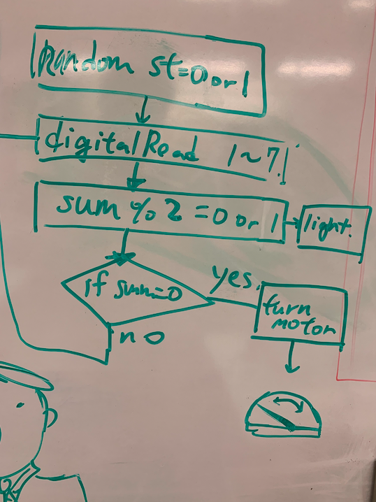
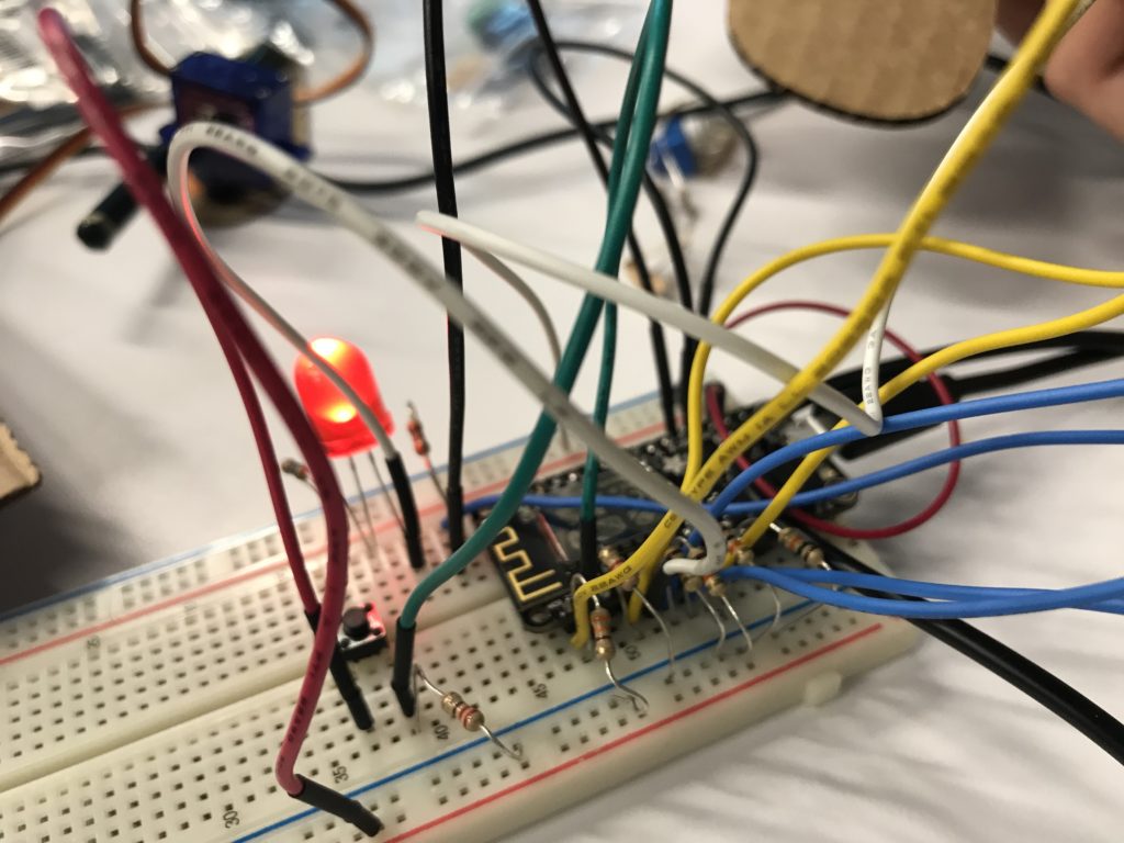
Coding Draft
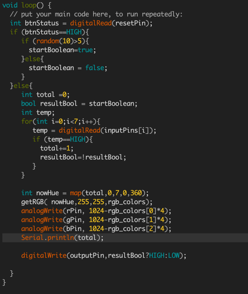
Code
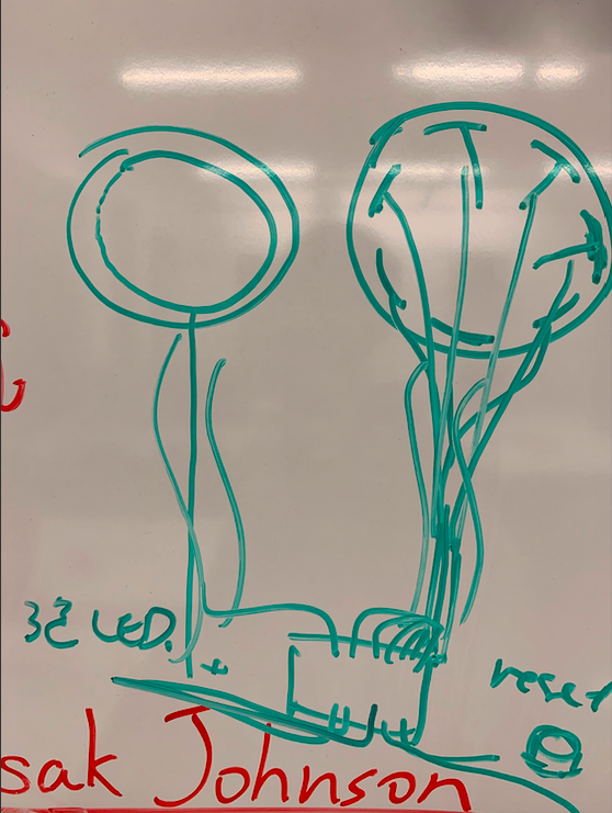
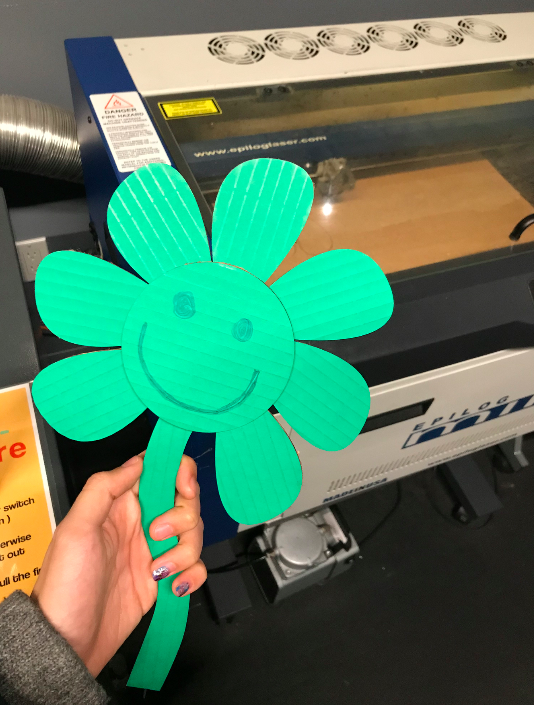
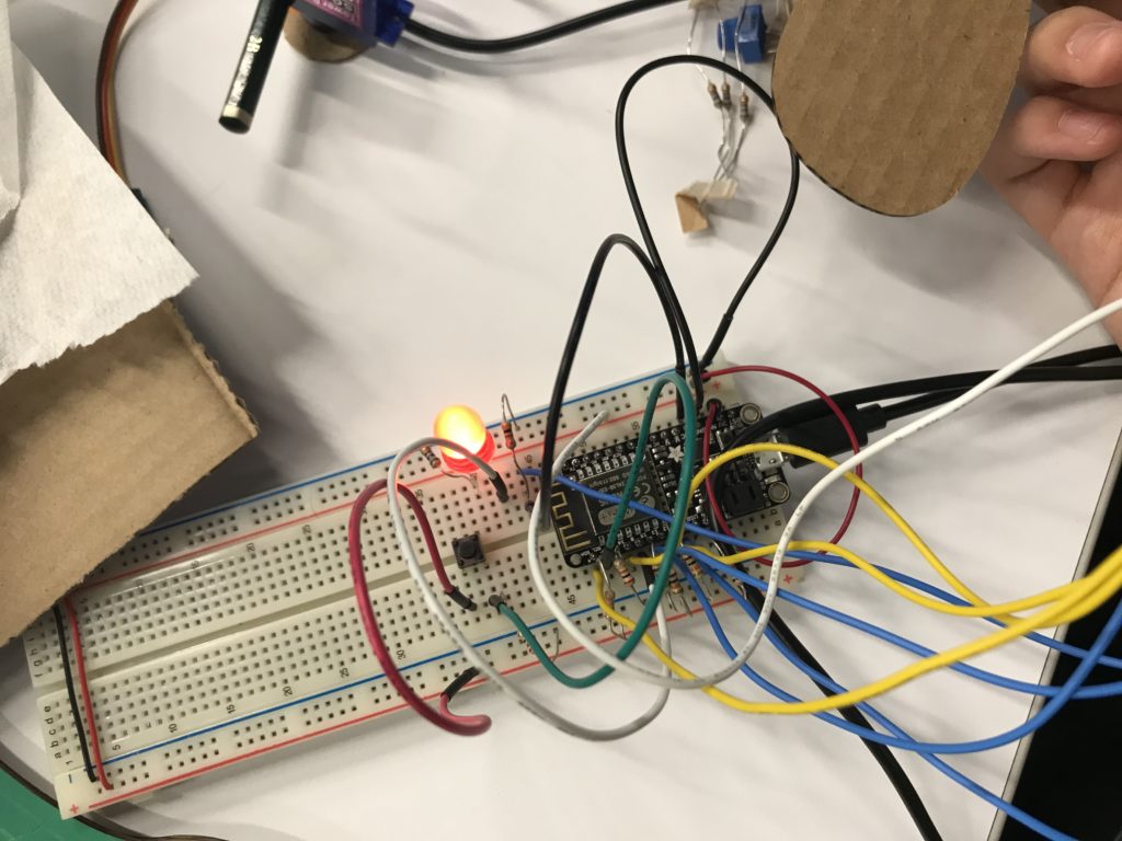
prototype
prototype
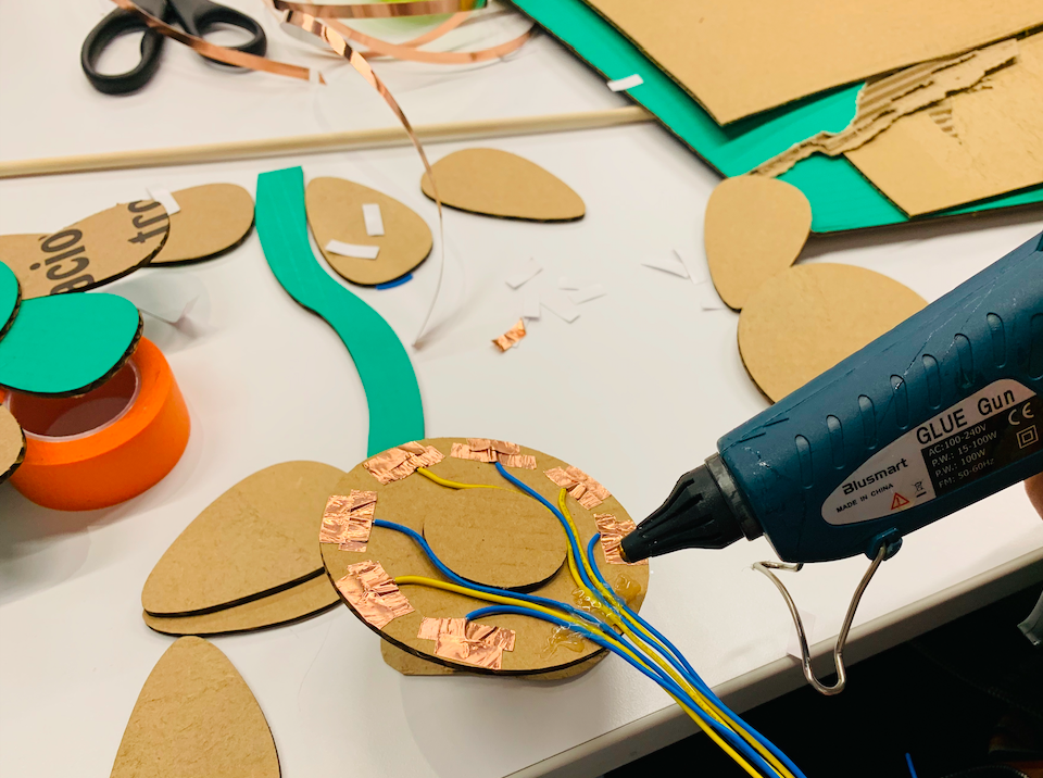
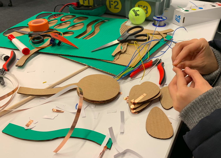
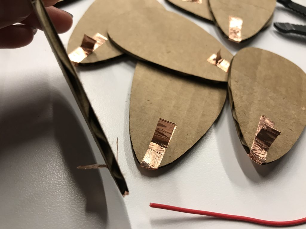
However, we don’t have any testing video at this point, because we have failed to make the entire flower conductive. We use mainly cardboard and copper tape for both prototype and the final version. As we were testing each petal’s conductibility, not every petals work. Instead, only two of them works well. We tried to add more conductive layer to the attached surface to make the rest petals conductible , but it didn’t work as we thought. So our next step will be finding out the conductive problem, solve it, and make this game happen with our love machine.
Conductive petal
(Update Feb. 22)
In order to solve the conductive issue, we folded copper tape into a special shape and sticked it on each petal. As you can see in the attached photo, the attachable surface becomes wider and thicker.