
Concept
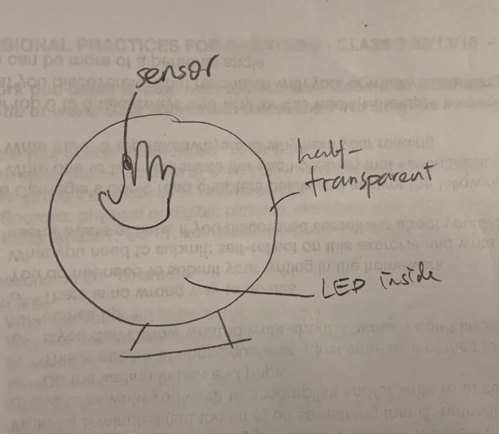
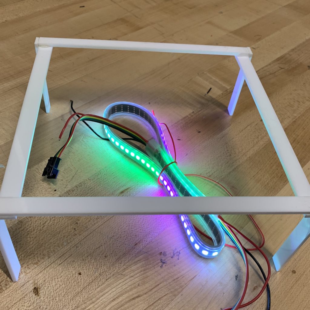
A half-transparent box with a pulse sensor on the surface. The LEDs will light up with the heartbeat and change color based on different bpm.
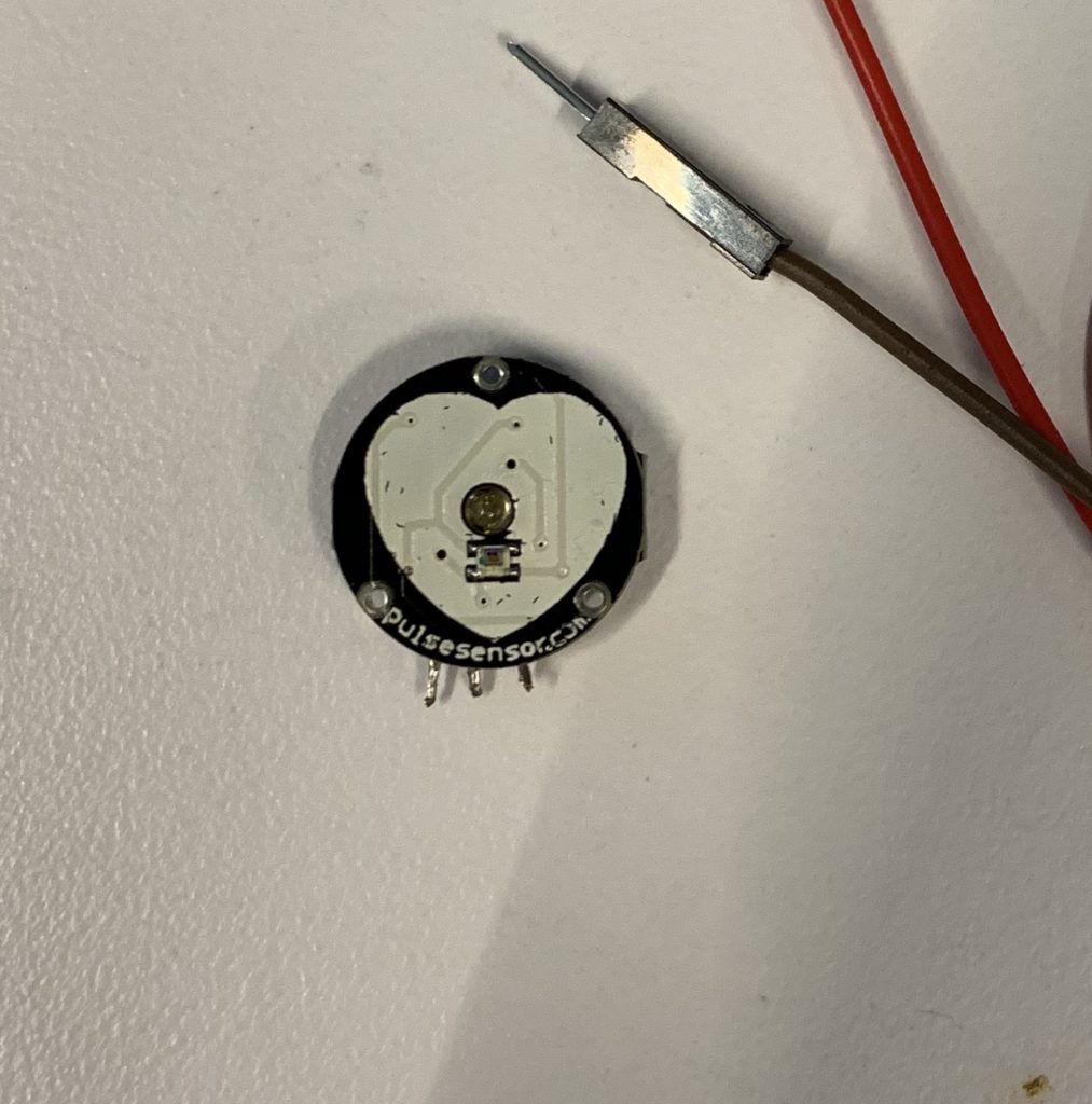
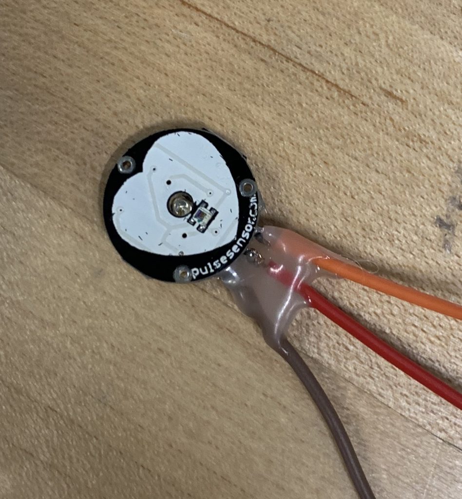
Pulse sensor
Instruction: https://docs.google.com/document/d/1d8EwDcXH1AZpIpEnrET28EBgStrbkbppxjQZcNRAlkI/edit
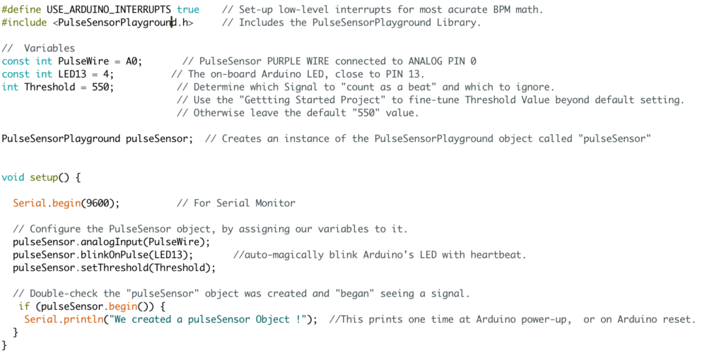
-Example code for blink led with heartbeat

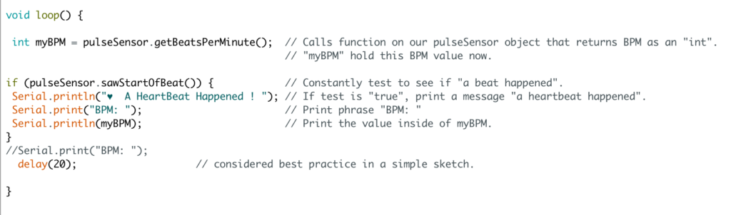
-Example code for getting BPM
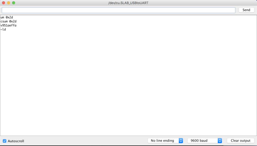
What I got in serial monitor
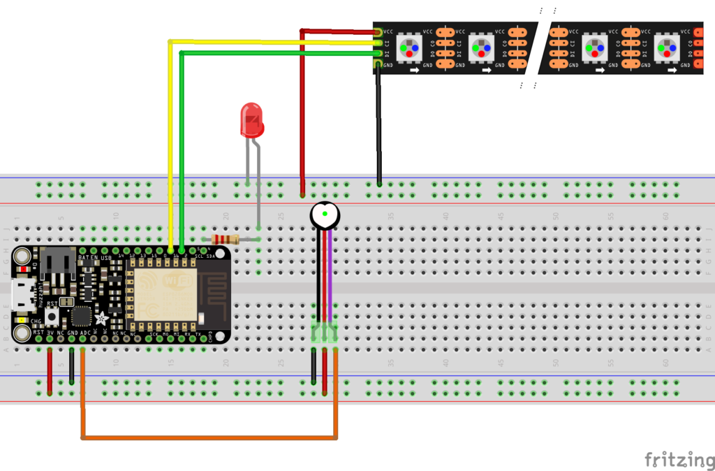
Wires
Video
Combined code
https://github.com/yueningbai/Love-machine/blob/master/2_21.ino
Hi Yuening, this is a great idea, though it looks like you may have bit off more than you could chew for one week, there’s a lot in here.
First, when wiring up any analog sensor with the Huzzah Feather boards we are using, you need to build a voltage divider for the sensor, otherwise it will be sending out too much voltage to the microcontroller and the readings will be off. Remember how the potentiometer had to be wired with resistors? ( https://raw.githubusercontent.com/IDMNYU/Interfaces-and-Net-Devices/master/week%203%20-%20analog%20in%3Aout/pot%20plus%20LED.png )? This is similar. You need to drop the voltage going into the microcontroller or your readings will be all wonky.
I’m not sure what you’re trying to do with the LEDs.
Did you try each part on its own? That is, did you test the LEDs alone to make sore they were working, and did you test the sensor on its own to make sure it was working before you tried combining them? If not, go back and try that first. Make sure every part works on its own before you start mixing them together.