For my midterm project, I wanted to make a piano using a p5js sketch, the aRest library, and physical buttons in order to control the p5 sketch. Curtis and I had difficulties while working through the project. We wanted to just aRest but we couldn’t retrieve the IP address of the microcontroller in order to set up our p5 sketch. Our problems were on the software side of the project and before the next class, I hope to finish this midterm project completely using the aforementioned methods. Below is a picture of our project, which I would want to improve with more work.
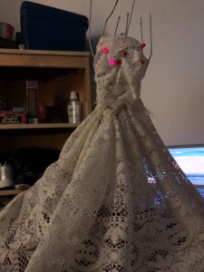
Something I have always wanted to know more about was wearable technology, and once I had to finalize something for my midterm project, I decided to try making a mood dress where different colour LEDs would light up when the button was pressed on the website it was connected to. But since I faced a bunch of problems, I dumbed it down to a much simpler form with six LEDs in total.
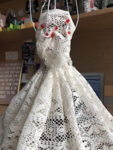
This is what the model “dress” looked like without any of the wirings.
The bracket (not shown) was made of thin wire hangers cut and stuck to a brown foam base with a glue gun. They were brought to a sort-of humanoid shape with thread (both the glue and solder weren’t sticking) and the white lacey cloth was strung together in two parts: the top bust (stitched) and the bottom skirt (pleated and stitched) and were attached to the bracket with more thread and some glue.
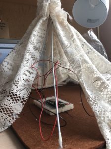
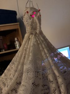
Next, the wiring was done. I tried setting up multiple colour LEDs, but it wouldn’t work with more than one LED in series for the yellow or green colour, so I stuck with the red. According to the current reading, only two of the red LEDs could be added to a single output pin. This is what the wirings looked from inside and the LEDs look like attached from inside to the dress.
One thing I had really wanted to do was add the LEDs in a particular pattern so that they look neater when lighting up, but because of the mess inside the dress with the wires, I couldn’t insert the LEDs to the pattern I wanted it to be in.
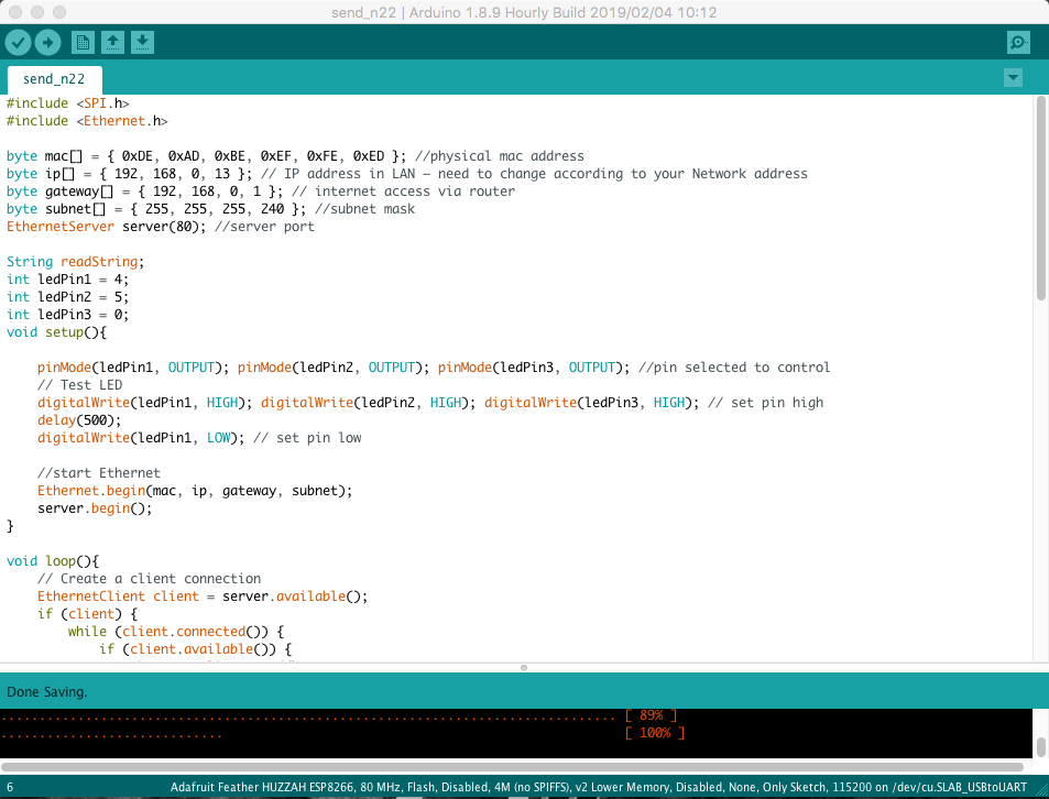
For the code, I used the Ethernet shield over the Serial Peripheral Interface rather than the aREST library because I thought it was easier. This is a section of the code.
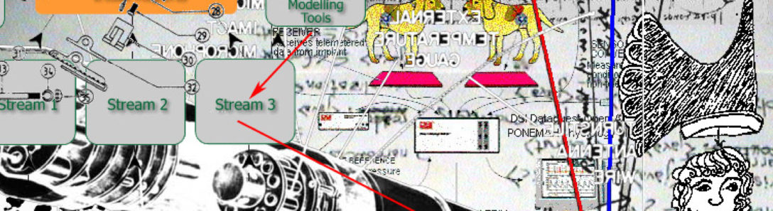
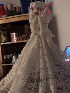
After being set up, these were the three settings of the led that lit up. Since there was only one colour LED that I could use, I thought of using sections rather than colour.
After this project was over, I realized there were many aspects to it I would like to improve later on if I had more time, like the overall look of the model, the number of LEDs, and even work on different patterns with the different lights and maybe incorporate other colour LEDs by removing them from series to match up the current.
As I mentioned last week, Jorge and I wanted to connect our micro-controller that would work as a piano. We would use the p5js library in order to get the notes of the piano to come out for each individual switch. However we came across many roadblocks along the way.
Our first major roadblock was that there was something wrong with both of our micro-controllers. When we were trying to upload the aREST code onto our boards but we were both getting errors on BOTH of our boards. When would check our serial monitors, the compiler was just outputting random letters. It would output things such a “cw$ ^42&*&”.
We didn’t think anything was wrong with the board since the code was uploading fine onto our boards. So we
Originally, my plan was to create an IP blocker where it would block specific websites using the Arduino as a hub. Think of it as an EMP for specific websites (YouTube, Crunchyroll, Facebook, Reddit, etc). However, I had way too many complications with this sort of build, as the Arduino is commanded using C++ in the IDE. The code would have required some form of Python that I am not accustomed to so I decided to scrap the idea.The next plan was to create a timer to prevent my problem with Procrastination. I eventually scrapped that plan as . I ended up trying to design a board that would randomize YouTube links each time I press a button. YouTube is my daily media source, so I thought this project would be nice to play around with.
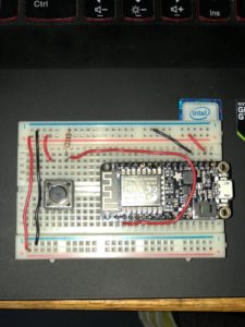
(Excuse the messy wiring.) This is the breadboard that ended up as the final product. The hardware side of this project was the most simplest part of the project as a whole. Unfortunately, I was not able to get it work the way I wanted with the code that I had written. I got the micro controller to connect to the internet and post a website, however I wasn’t able to figure out how to randomize different YouTube links. I will try and figure out how to do so, but am not able to provide code at this particular moment.
If you would like an idea of what I was going for, I found a website with the exact idea in mind: https://ytroulette.com/
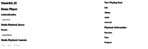
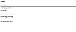
From last week I learned that I needed to use a CDN in order to get the webpage to load properly on my computer’s browser, so I started with getting that to work. I was surprised to learn that apple already has a CDN for Apple Music so I started implementing that into my website. https://js-cdn.music.apple.com/musickit/v1/musickit.js You can use the JS api through this version and made things a lot easier because I could then reference those from declarative mark up elements where all the hard work was already completed for us. The markup elements do some of the tricky parts especially with interacting with the microcontroller in a webpage setting because it already starts to look like some sort of player but more barebones. This demo player was good but it had more information than was really needed and could’ve been clearer to the user on what it should be.
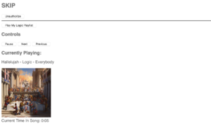
From here I refined it from just picking a random apple playlist to one of mine and getting it to correctly work. I found the playlist identifiers and chose a specific one to try out with this player. I styled it and added other pieces, and just as importantly removed things that weren’t as important to 1. keep it a lightweight player, and 2. not distract you from the point in the first place which is, it’s suppose to be in the background.
This is what it turned out to be. I had issues getting the authorization through apple’s services to work on the microcontroller because if I set the controller to refresh, it would immediately unauthorize, drop the queue of the songs and start again. Even if you started playing after awhile. So then I started looking into keep-alive connections because the microcontroller was purposely dropping a connection after 5 seconds even after I didn’t tell the client to close. It became harder and harder to get the microcontroller to register the button clicks to skip because it would do it only after the connection was dropped. I looked into other web libraries for the esp8266 on github but after trying it out and looking with the other issues people had, the controller always overrode and closed the connection after a couple of seconds. I really want to be able to build this the proper way and get it working but in order to do so I have to do it somewhere else. However I was very proud that I was able to get a player to properly play my personal playlist from apple music and host it on the microcontroller.
As stated in my previous post, I attempted to build a Pomodoro productivity timer.
Equipment:
1 x Feather HUZZAH ESP8266 microcontroller
2 x LEDs, red and green
2 x 220-ohm transistors
1 x standard 16×2 LCD
iPhone to provide WiFi hotspot
Wire, etc
After multiple unsuccessful attempts to wire up the LCD, I pivoted and elected to use 2 LEDs instead, red indicating shorter break time, and green longer work time. My timer function itself is a simple loop that runs on the background. I have yet to figure out how to set up communication with the server so that the timer starts at the click of the button on the webpage. I will need to utilize a function without delay() to achieve that, and perhaps explore timer libraries for Arduino.
In demonstration videos, I left in the LCD in the breadboard setup. I will attempt to get it to work in the future.
The videos above are demonstrations of the function of the prototype and the programming.
So for my midterm project I envisioned a button that would communicate some sort of message when pressed a certain amount of times. Lets say, 3 presses would say “I need to use the bathroom” and 4 would be “I’m hungry!”. This would help people who need assistance to do something. Depending on the number of presses a different message would pop up on a screen somewhere on a web page. I could use the serial monitor in order to display the messages, but I couldn’t get messages to display on the html page. Maybe because of a fast refresh rate of the page or something in my code. But I kept getting stressed about why my code wasn’t working.
So while I was thinking about what to do, I thought about the Lifeline commercial where old people fall and they say “Help I’ve fallen and I can’t get up”. I don’t know why, but I thought that was kind of funny because how fake their acting is in the commercial and the memes that came from it. So I decided to make it display at least that message.
The is my breadboard set up for this project.
My code for the set up was pretty simple and I’ve included it in a github here, https://github.com/ninjadan56/Midterm-Net-devices.
My web-page was real simple, it only displayed LifeLine and then waiting for response right below. When the button was pressed it would display “Help!”. This is a video of me demonstrating the button.
As I mentioned last week, In my midterm Project, I want to make a spider that can climb up and down when someone approach and make noise, it will climb down from the ceiling and observer what is happening then report to the master.
Spider and the microphone
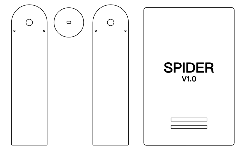
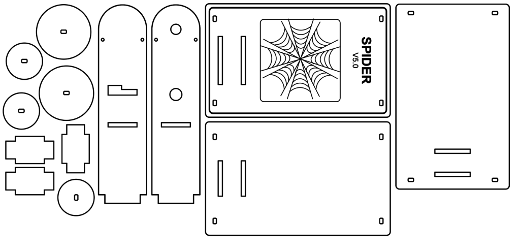
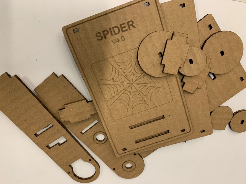
Physical Holder part
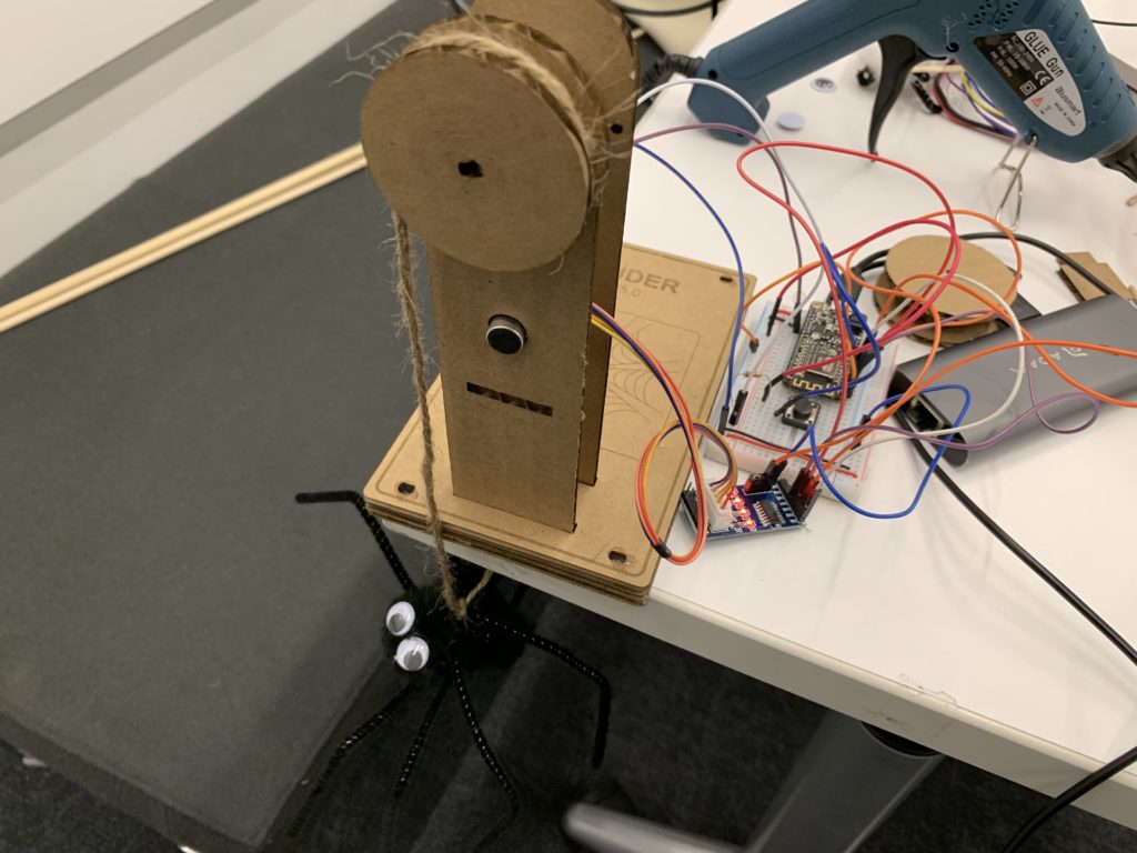
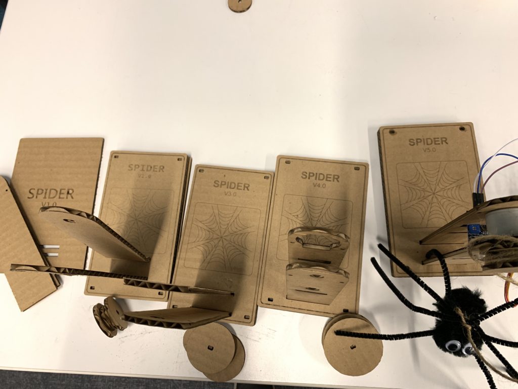
For the physical device part, I use cardboard + laser cutting to make my wheeling holding device, After the fifth iteration, I finally succeeded to integrate the microphone, the turning wheel, and the motor together. I found that if I want to assemble the components without glue, I have to calculate the burn-out width of the holes and it is hard because each time I cut, I get a different result.
First version that cannot even stand wellFinal version that can be assembled and has a nice looking
Micro controller: Stepper Motor and Sensor
I use a stepper motor and cannot get it working in both directions for 3 days. Finally, I found that the motor 28BYJ-48 have to use a different library which is <CheapSteaper> or it will not output the correct signal, which causes the motor to work both clockwise and anti-clockwise. Originally, I plan to use motion sensor for detection, but I didn’t have one so I change it to the sound sensor borrowed from the Arduino kit.
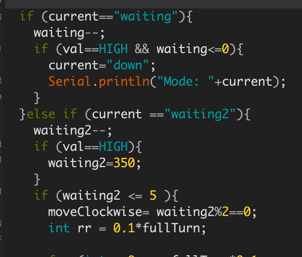
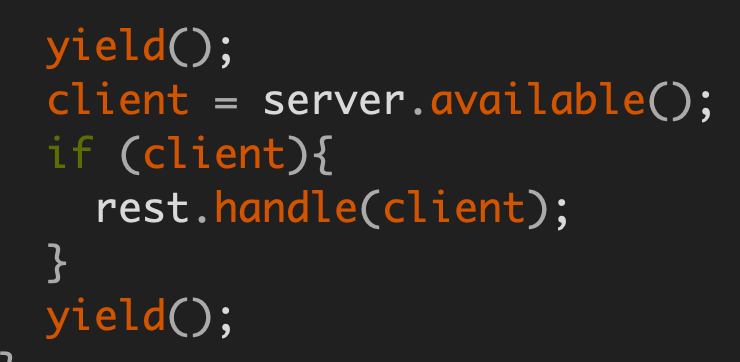
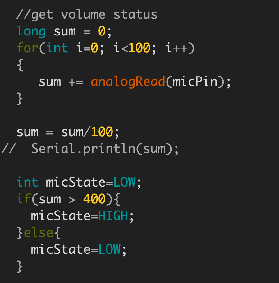
In my Arduino code, I use a state machine structure to control the spider’s motions. There are four modes – “waiting”, “down”, “waiting2” and “up” which are correspond to the complete cycle of spider waiting for some noise, climb down when it hears something, stay at the bottom to observe and climb back to the top. It is very playful that when the spider hears some noise. Also, there some small challenge in the development process, e.g. I have to sample analog input from the microphone 50 times and get it’s average to avoid instant peak, and I also find that I have to at yield twice inside for loop which allows aREST library to get and response to new requests during manipulating the stepper motor.
State Machine
yield for handling requests
Avg of microphone input
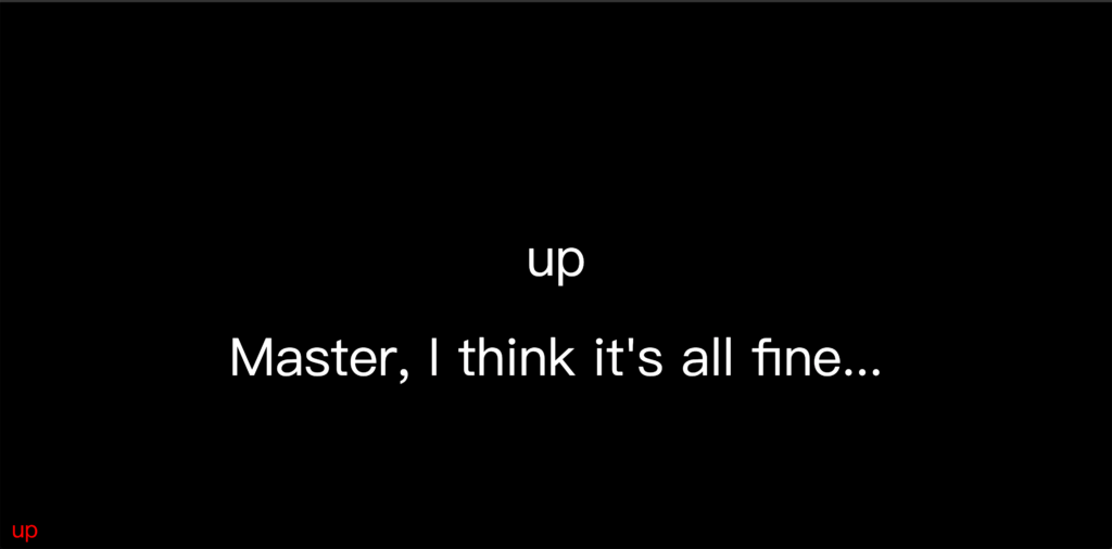
p5.js Interface for monitoring
I made a small p5.js sketch that shows the spider’s status. When the spider climbs down to see what happened, it will show a rotating eye animation on the screen. After 5 seconds, if there are no additional sound, the spider will report it is safe then climb back to the top to keep monitoring.
no one’s there
climbing up
climbing down
Rotating Eyes
Demo
If I have more time in the future, I want to make a spider that carries an ESP8266 and can remotely control by the computer and has some default state inside the micro controller. It’s a very playful experience for me to work on the prototype for such a long time and conquer the lazy and fear to improve the structure again and again.
For my midterm project, I initially wanted to make a drum machine. I believed that the program p5 would work well for this. The p5.sound library has a lot of musical examples for inspiration, and I’ve worked with p5 before.
First, I made a p5 sketch that allowed me to play drum sounds and loops by pressing keys on my laptop. I had 8 different drum sounds that I could trigger by pressing the keys “a” to “h” on my computer. I also had two loops that you could turn on or off by pressing keys “z” to “v”. I did a run-through of that in 0:02-0:14 of the video below.
Next, I wanted to create a physical interface that would be easier to use. I wanted to use large button switches to trigger drum sounds and loops. I believed they would give a more natural tactile feel. To do this, I created an Arduino sketch that could draw information from button switches in real time. Then I wired up 8 button switches. I wanted to transfer the data about the microcontrollers from my Arduino sketch to my p5 sketch. I used p5’s built-in loadJSON function to get data from my Arduino sketch through my web browser. At this point, I ran into a problem. I couldn’t figure out how to get my p5 sketch to draw information from my microcontroller in real-time. When I ran my p5 sketch, I could trigger a drum sample if I pressed down on the button switch before the sketch finished loading. But after that, I couldn’t use the button switches to interact with the sketch. Also, the drum sounds that I tried to trigger would buffer, distort, and play indefinitely. Basically, the sounds would glitch.
I decided to rename my project the “glitch machine.” Glitches can sometimes sound cool in music. For example, there is a style of EDM called glitch that uses the effect as a rhythmic device. Glitches are also sometimes used in post-rock and alternative rock as a sound effect. I decided to see if I could create interesting sounds using my glitch machine. I put drum, guitar, bass, and keyboard sounds in my sketch. While it’s not what I initially intended to create, I think my “glitch machine” has the potential to create interesting sounds. I did a run-through of this from 0:20 to 0:30 of my sketch. I used the refresh button on my web browser to switch between different sounds. For this reason, I had to record the audio and visuals separately: I couldn’t press refresh, press down on buttons, and hold my phone to film all at the same time.
To recap, my project is a tool for librarians to help manage the noise level in their library. I originally set out to build a tool that was automatic, which essentially would become the librarian itself. In my first iteration, I was still waiting on a part to arrive, the electret microphone. It was the only microphone I saw on Adafruit, so I assumed that it would be simple enough to use – there were only two wires.
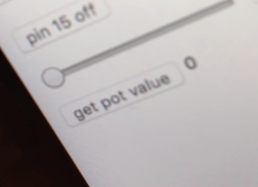
The part came in, and I constructed my circuit, and in testing the microphone was only giving me a reading of 0.
I thought surely I had a wire misconnected, or there was an issue in my code somewhere. I was yelling into this tiny mike while taking readings, and occasionally it would jump up to 1, and once I saw a two, but I soon realized after yelling that it would still do this, which must have just been the natural oscillation/inconsistency of the reading. I began to research this more and I finally found out that you need a significant amount of power to boost the signal you get from a microphone. It needs to be amplified to a level that can be read by a microcomputer. A comment on the Arduino forum said:
“The idea is to amplify the signal from the microphone, which is in the millivolt range, to a level in the 0..5V range, that can be converted by an analog input of Arduino.”
This required a complex circuit with parts that I didn’t have, so I had to pivot on my idea. It still would have the same functionalities, but instead of being triggered automatically, the librarian would trigger them from her desk.
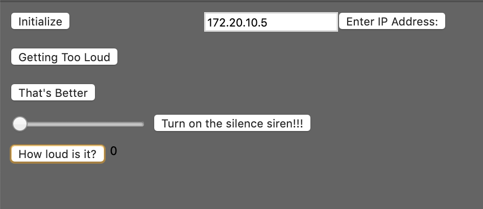
The Librarian would need to enter the IP address, and set up the required ports as outputs (“Initialize”).
If it’s too loud, they would hit the “Getting Too Loud” button and the red LED light would come on.
Once the children quiet down, the Librarian would hit the “That’s Better” button to turn off the LED.
If the children refuse to quiet down, the Librarian would have no choice but to turn on the “Silence Siren!!!” to out yell the children. They could control the tone played with the slider, to make it more irritating or less irritating depending on how they are feeling. Demonstration below: