Final_emoji

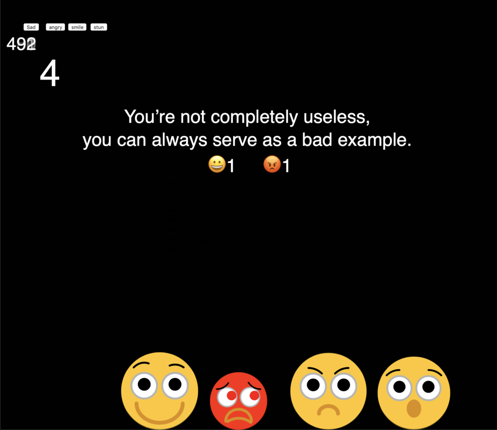
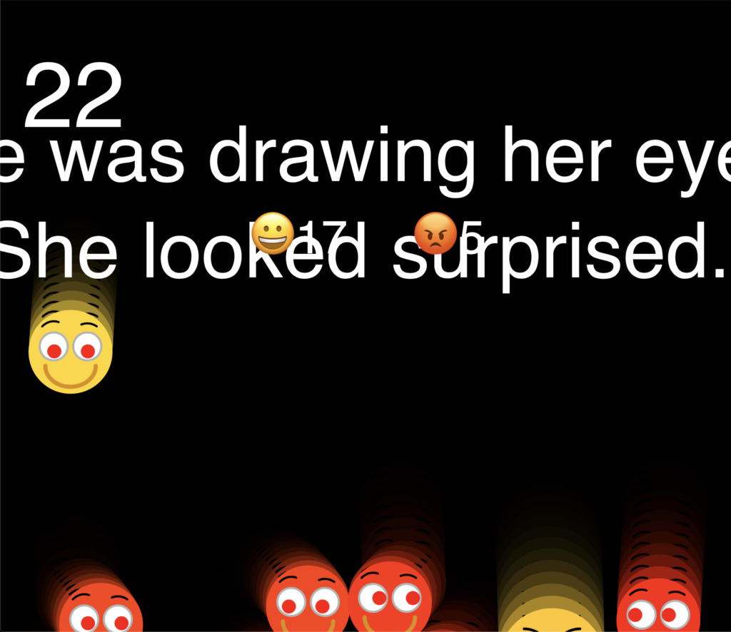
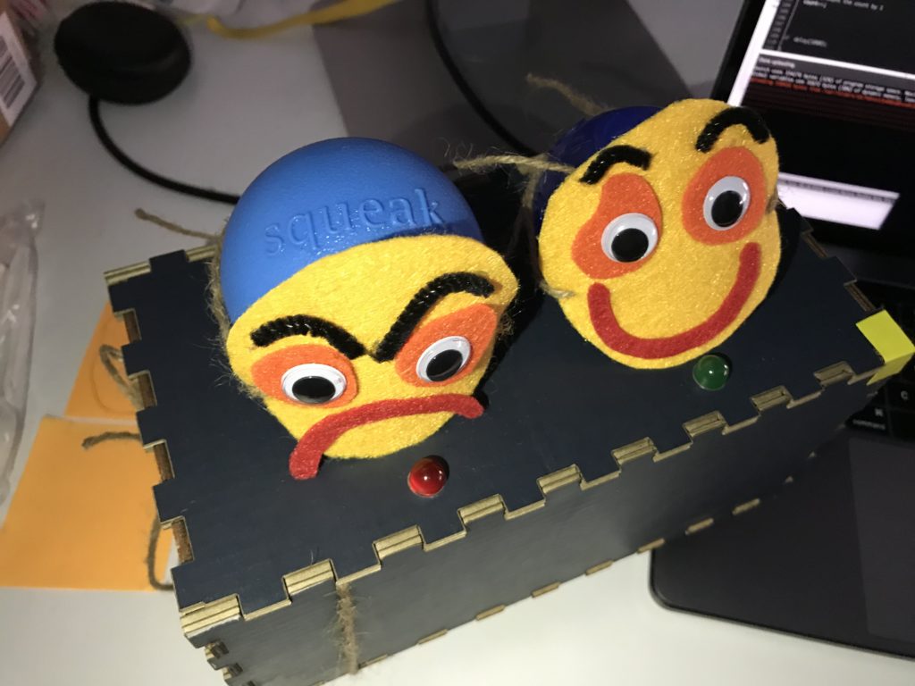
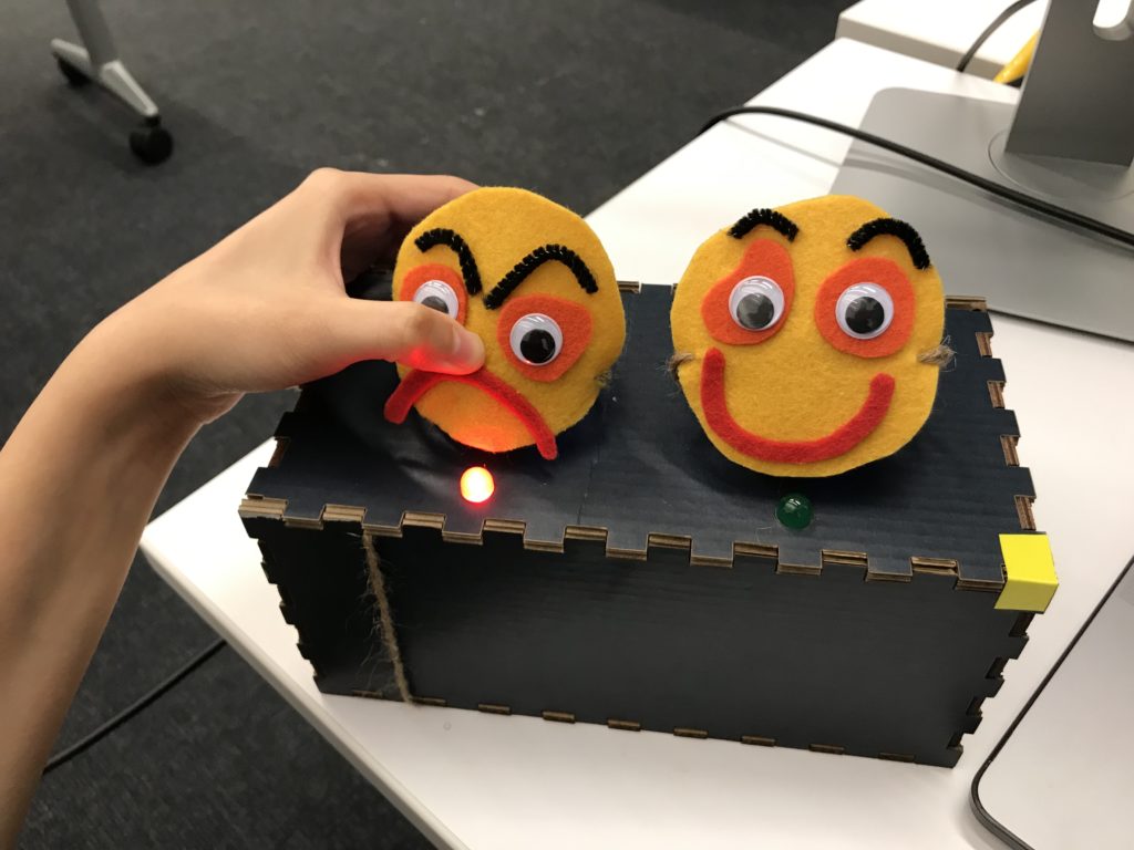
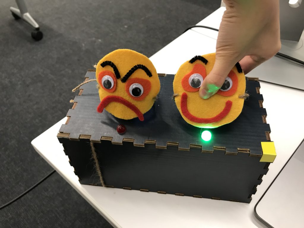
For my final project, I create a physical emoji, which allows people to emoji react to jokes by physically squeezing it and making a squeaking sound. A joke will be shown on the screen, and people can squeeze the emoji to drop down and express their emotion to the joke.

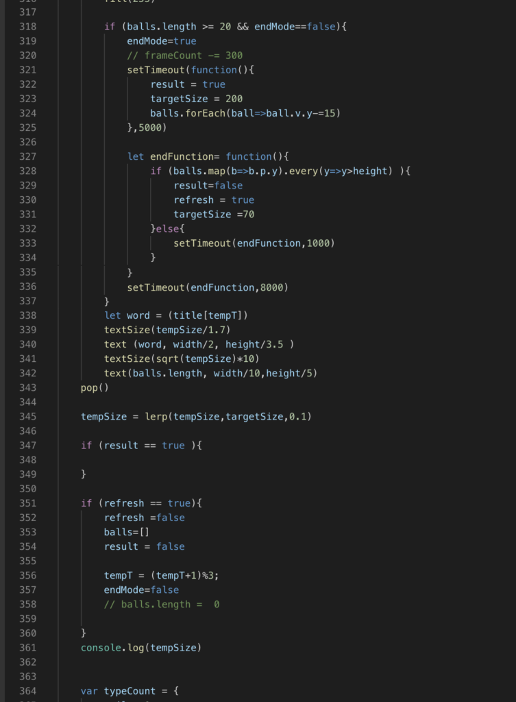
In order to avoid the screen being filled up and the joke covered by the emojis, p5 will stop renewing data once the maximum receiving number is reached. Once the maximum is reached after 3 seconds, all emojis will bounce up and fall out from the screen. After all emojis have already left the screen, the joke will be renewed to the next one. The number of emojis will be reset to zero so people will be able to drop down new emojis again.

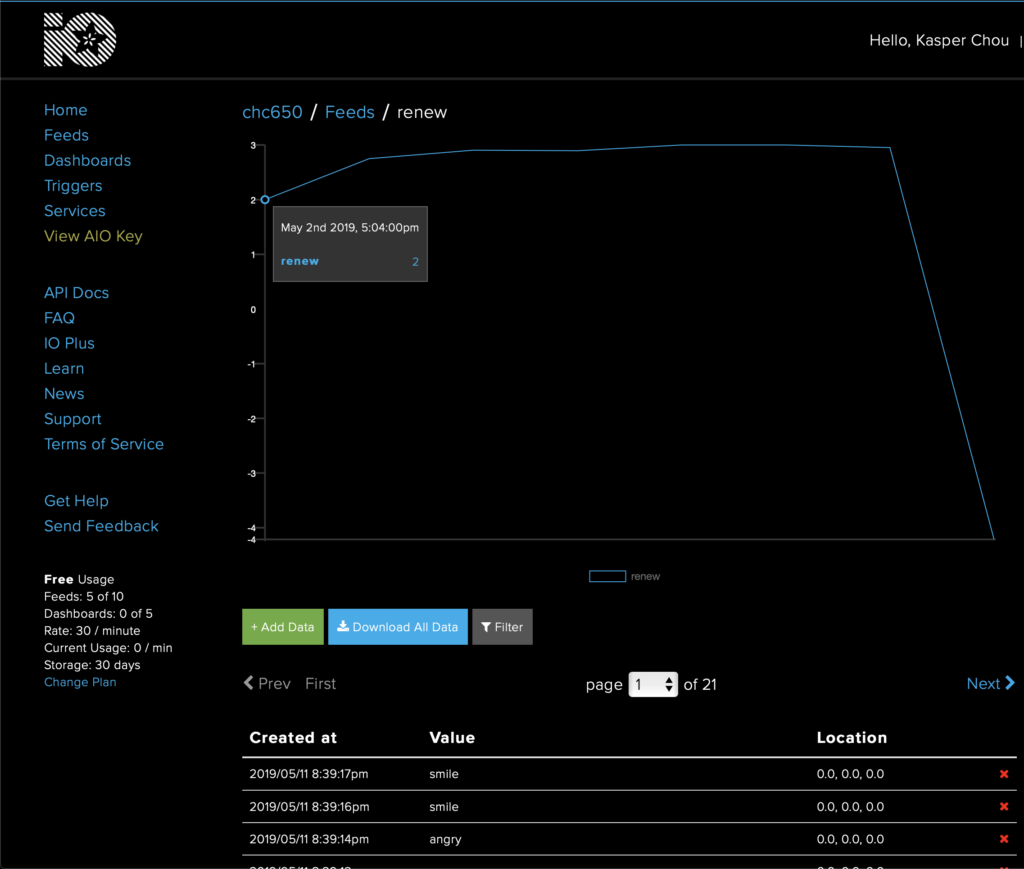
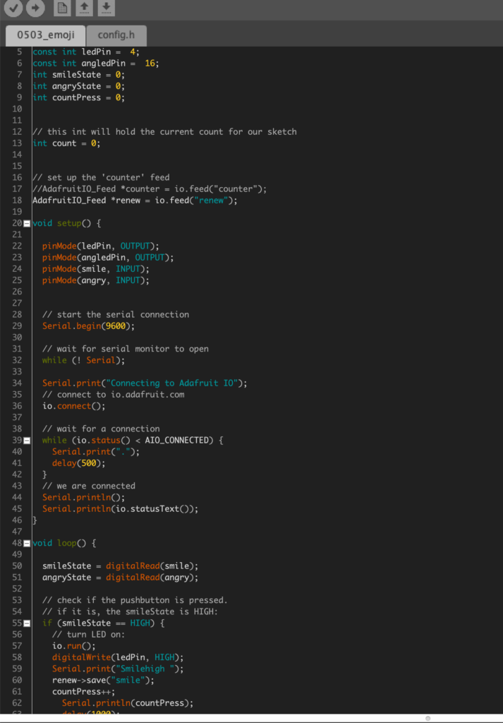
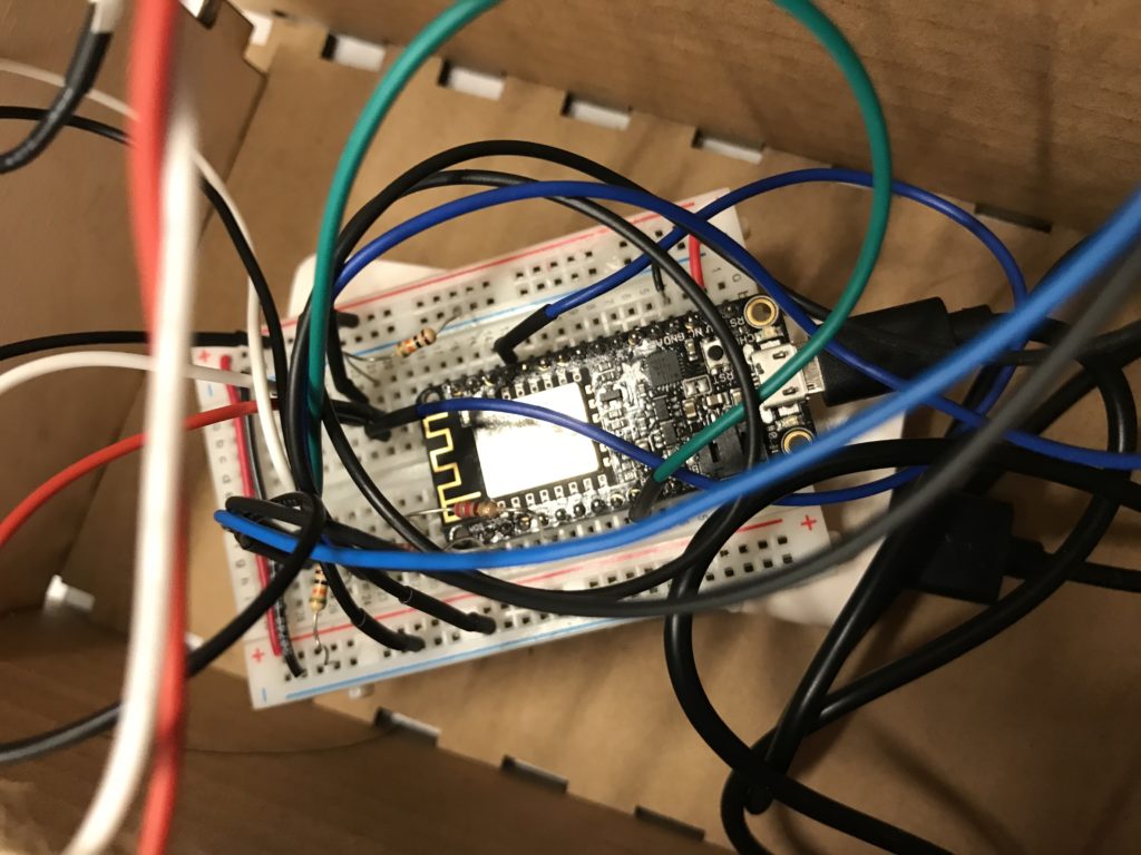
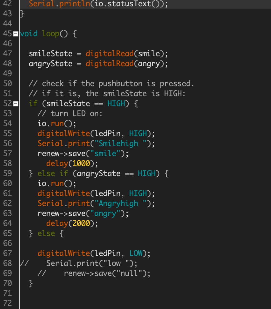
For connecting p5 and Arduino to make real-time interaction, I used Adafruit.io to send and renew input data.

At first, I was planning to create four different emojis (sad, curious, smile, angry) and each one has their specific way for interaction, such as squeezing for smile face (tilt or force sensor) or wiping tears for crying face (moisture sensor).  I end up with only two emojis, angry and smile, and both of them can be triggered by force sensors. I cut down to only two so people will be able to spend less time on deciding which emoji to drop and the interaction between two emoji can be noticed more obvious and easier.

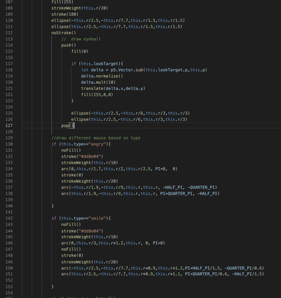
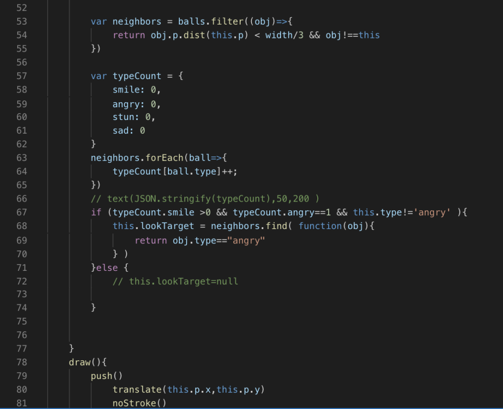
In order to represent how people react to the counterpart in the real world, I made the smiley face scale down and change its color when there is an angry emoji shown around them. The majority always tend to use an aggressive way to change the minority’s opinion, and the minority will possibly start to be afraid and stop speaking out their voice without hesitation or fear. 

I decided to use dog squeak balls as my physical emoji’s main component so there will be a goofy squeak sound when people drop down an emoji. And I place them on a box which I laser cut with four holes on it, two for placing emoji and two for LED light. 

The difficulties I met through the process are mostly from p5. The most time I spent on this is making emoji automatically refresh after the maximum is reached and switch to the title after every emojis has already fallen out from the screen.

If I have more time on this project, I would like to refine the physical part. Probably make the emojis softer and redo the box with wood board or acrylic board instead of cardboard. I’d also like to think about how to make the p5 emoji interaction more visually exciting. 

Final_update

For this week progress, I have done the p5 emoji interacting part, and control the dropping emoji with Arduino. I also decide to scale down to two emojis instead of four, although I have already finished their code. Only smile and angry face will be used because this can make the interacting part more obvious and easier to be noticed. In terms of the Arduino part, I have successfully connected it with my p5 file by using adafruit.io. I haven’t started the physical part yet, so I use two force sensors to represent two different emojis in the demo video, and I will be ending up using force sensors in my physical emojis.

For the next step, I need to finish the topic shown when the emojis are falling and the result page for p5, which will be showing after specific time of no one playing with it or after the screen is filled up. I will also have to refine the interacting part. As for the physical part, I will be starting with prototyping before my components arrive.

Final_Emoji Button

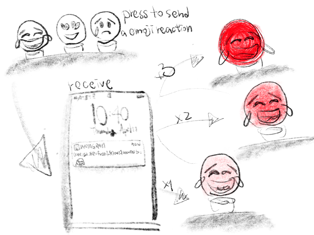
For my final projects, I have several ideas, but one of them is physical emoji reaction. Since Instagram has incorporated emoji reaction for Instagram story, most people start to react by only sending an emoji instead of context. In order to bring back the social media interaction, I’d like to create a physical device. It allows people to send emojis by pressing the button. However, before sending out an emoji, people are required to receive enough emoji from other people. The more emoji they receive, the more they can send out. To indicate the amount you got for each emoji, I will add a LED for each one; the more you got, the brighter the emoji will be.

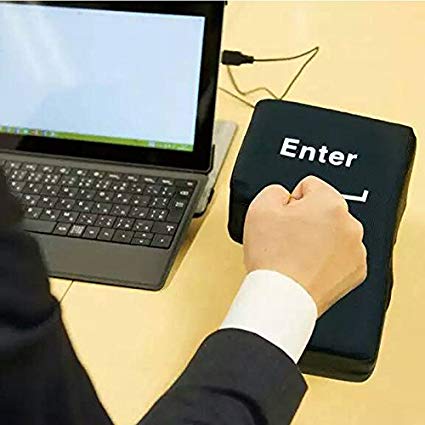
I haven’t figured out the exact way to link the physical emoji device with Instagram, but for the physical part, I will be doing similar to the Big Enter Pillow. Once the pillow is plugged into the computer by USB, it can be worked as the enter key, such as sending messages. As for mine, I will be doing in a wireless way, so the device can also be worked on phone. 

0405 Homework

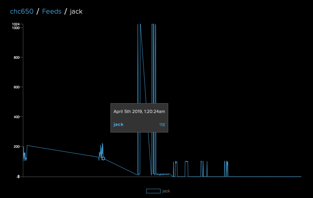
For this week assignment, I was trying to create a guest notification. Each time if there is someone stepped on or walked over the specific floor area in front of your room, and the pressure sensor senses it, you will get a SMS message that telling you someone has passed by.  I have started testing with a pressure sensor at this point.

An inspired artwork I found these days is the one I saw at Teknopolis 2019, which exhibited several groundbreaking multi-sensory installations. One of the most impressive artwork is the one that people could interact with the elements they drew on the paper. In order to start the interaction, people need to draw their own artwork by using black ink. After you are done with your drawing, you could leave your artwork under the camera for three seconds, and then you could start with playing around with the elements you drew by using your hand. The most intriguing part I found from this installation is actually the combination of visual effect and sound effect and how it successfully caught people attention among several artworks. For my final project idea, I haven’t had a concrete idea yet, but I would like to create a new device which could let people play around with their own work. It could be either combined with generative art or just physical interaction. The main purpose for creating this is that I’d like to make people feel the connection with network/ internet, and let them know they could actually interact with a device, not just feel the coldness from technology. 

Network Infrastructure

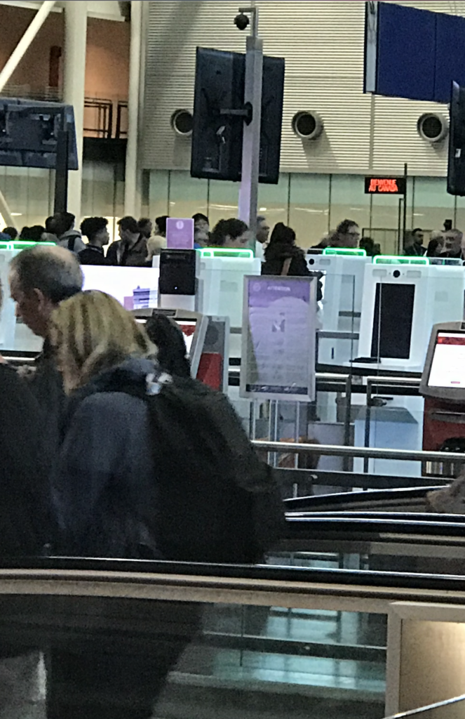
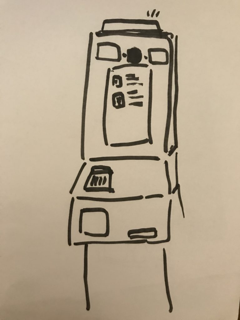
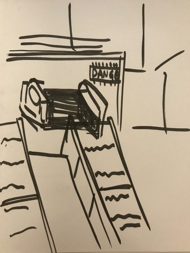
The first network infrastructure I drew is called primary inspection kiosk. I first saw this at Montréal-Pierre Elliott Trudeau International Airport, and I thought this could only be used by returning residents, Canadian. Surprisingly, all travelers, including foreigners, are required to verify their identity and make an on-screen declaration through this machine. During the self-inspection process, I found it easier and faster then I thought. People will need to scan their passport first, take a photo, and answer some questions. After using it, I personally hope that every international airport, especially JFK, could installed a bunch of this kiosk, so people do not have to stand in line for more than two hours waiting for the inspection.

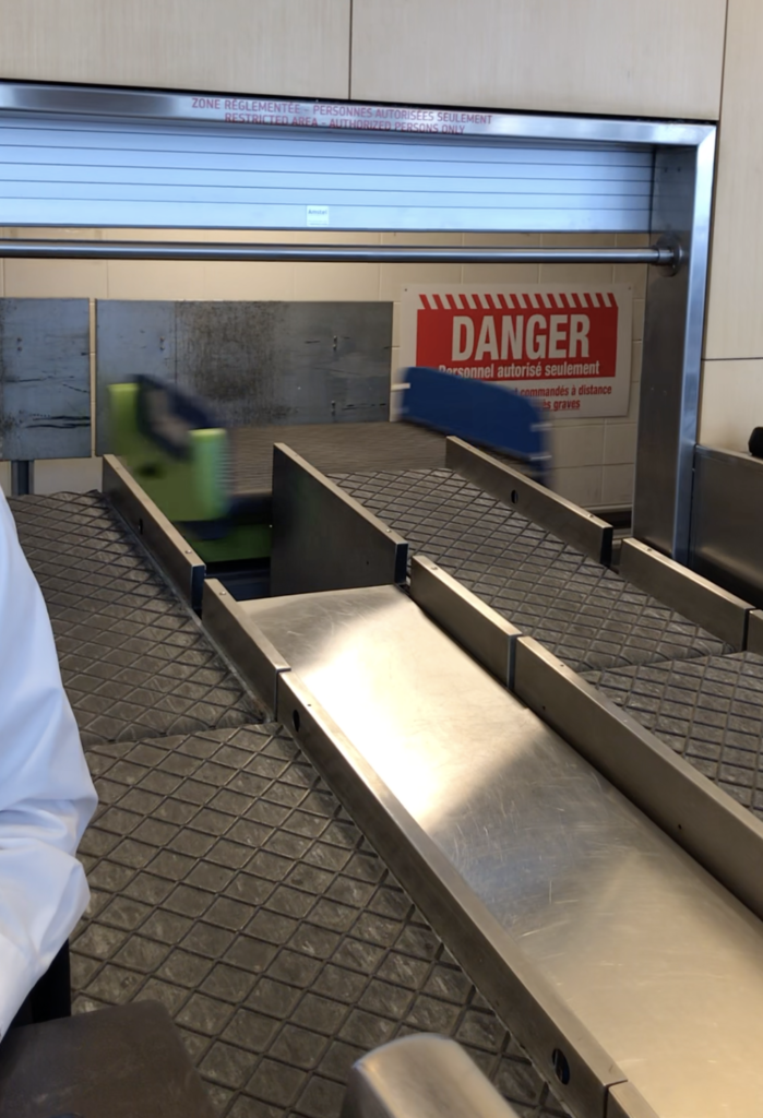
The second one is some cars for transporting check-in luggage. I saw them at Québec City Jean Lesage International Airport when I was checking in for my flight from Quebec to New York. Although I didn’t have any luggage to check in, I keep looking at this system. Passengers will put their luggage on the conveyor belt first, and when the luggage is sent to the end of the belt, the car will come and take the luggage away. In this way, there is no need for a person to stand there and move every passengers’ luggage by hand.

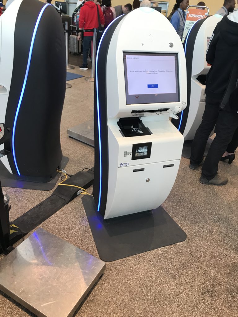
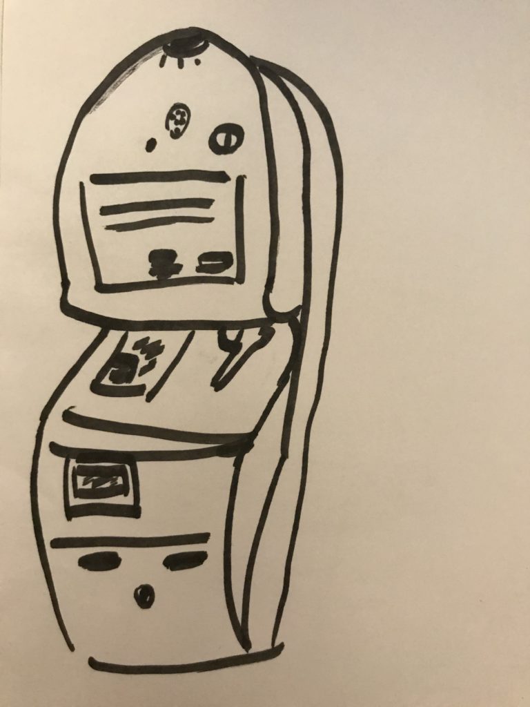
The last one is the self-service check-in machine. People have to select their airline first, and then either enter the booking reference manually or scan the QR code. After confirming your information and selected seat correctly, you will get your boarding pass and finish the check-in process. Although it seems simple, I and my friend didn’t successfully check-in by using this machine. The selected seat of one of us is Gate, which means you are possible to get on this airplane but not guarantee to have a seat, so we have to go to the ground crew for help. 

Midterm_Teletubby

Demo

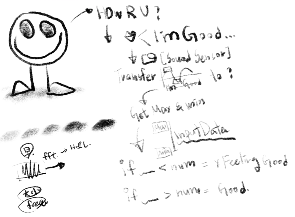
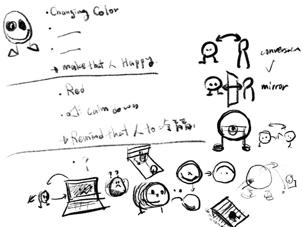
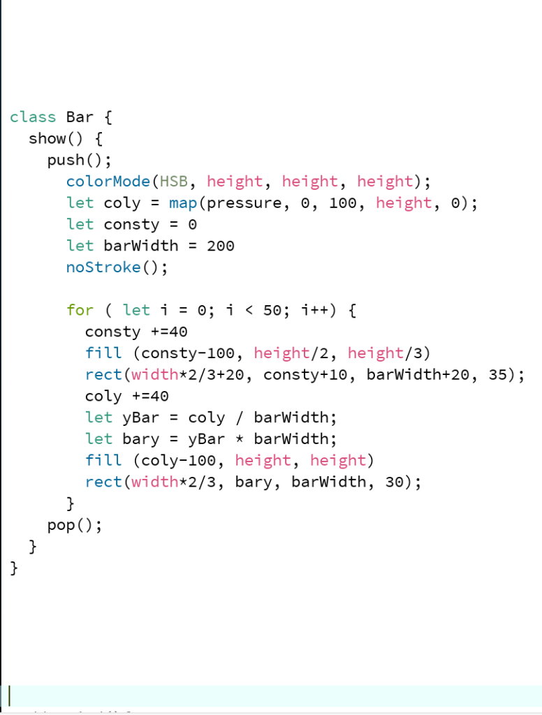
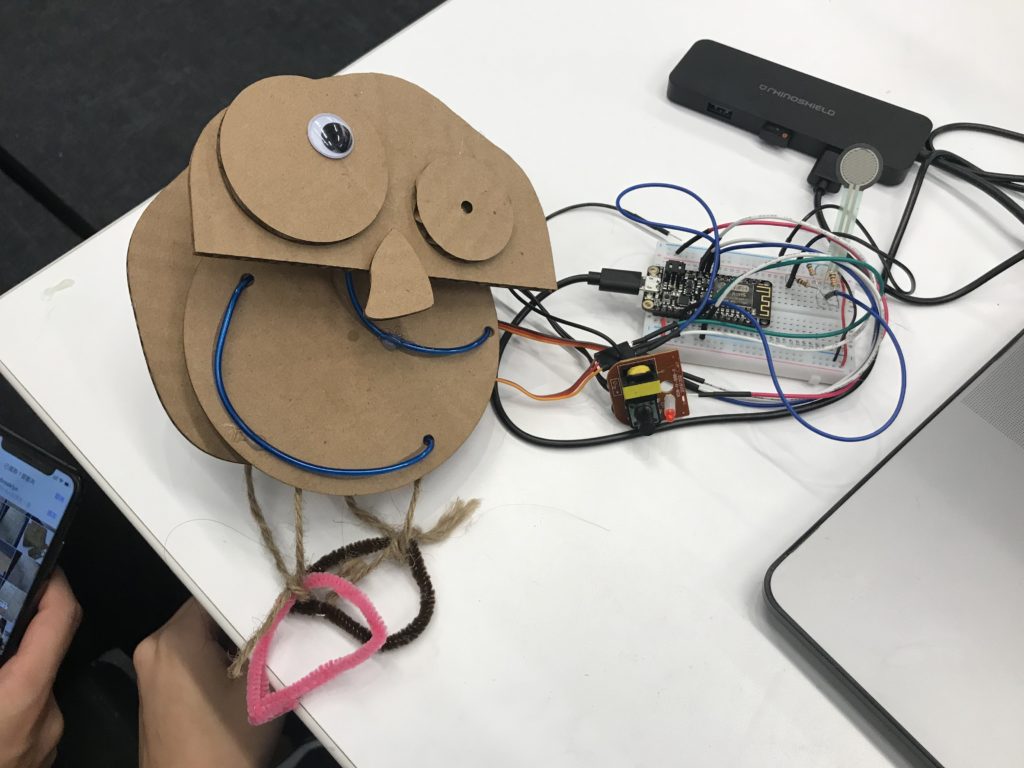
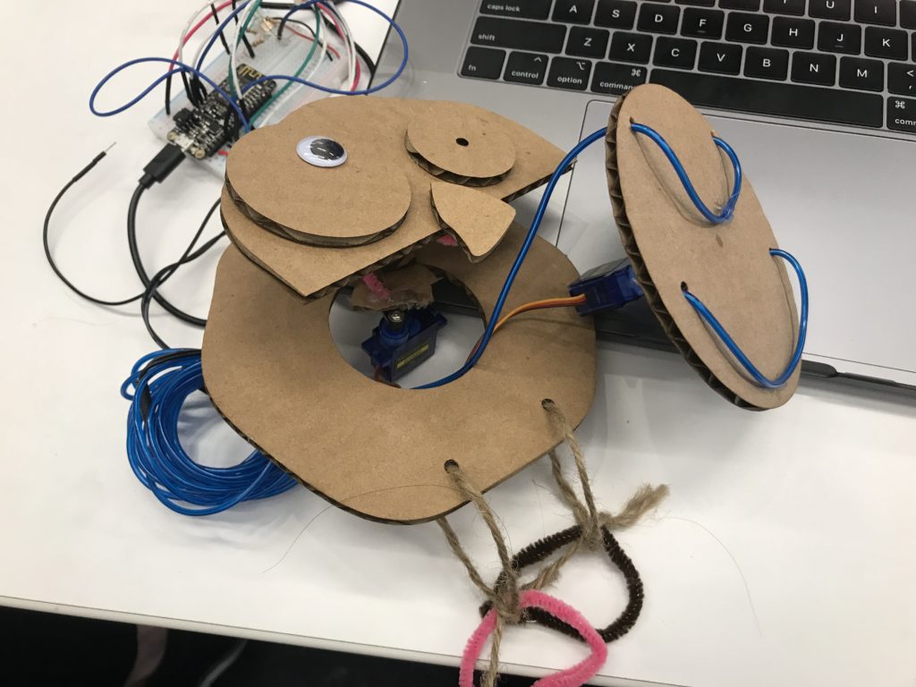
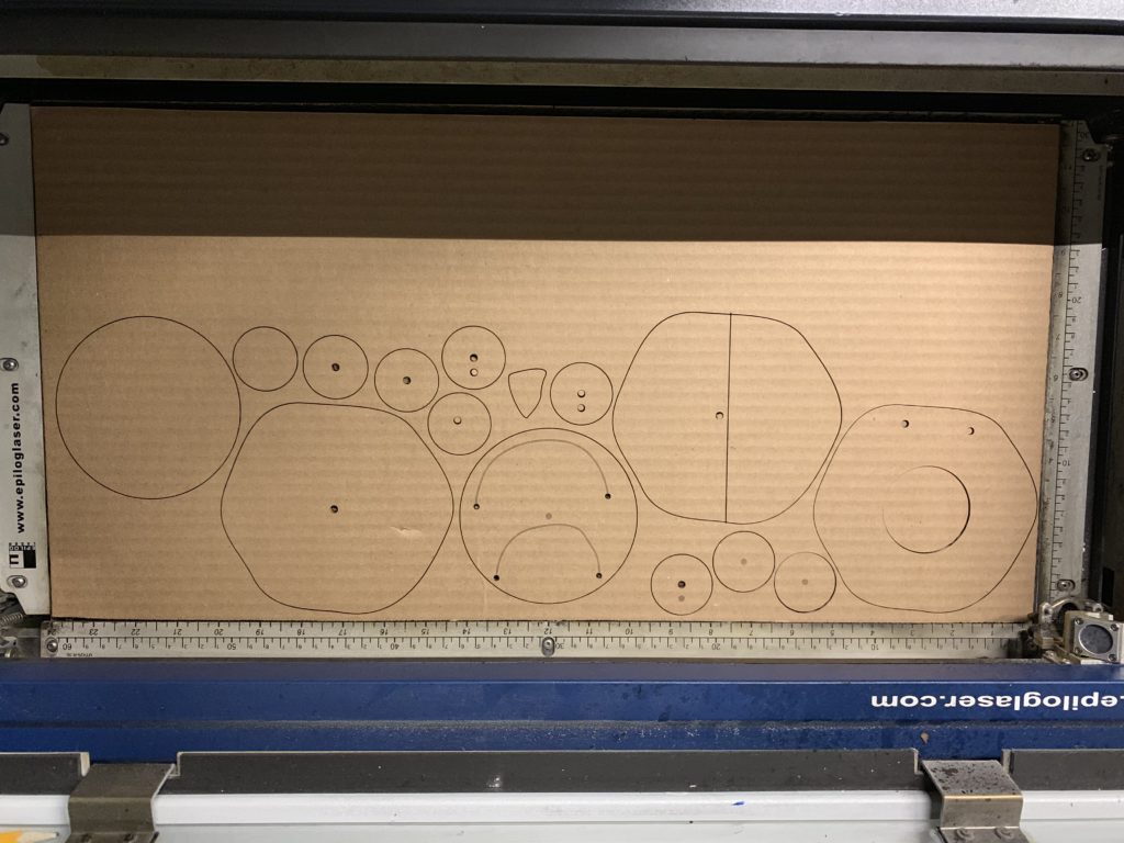
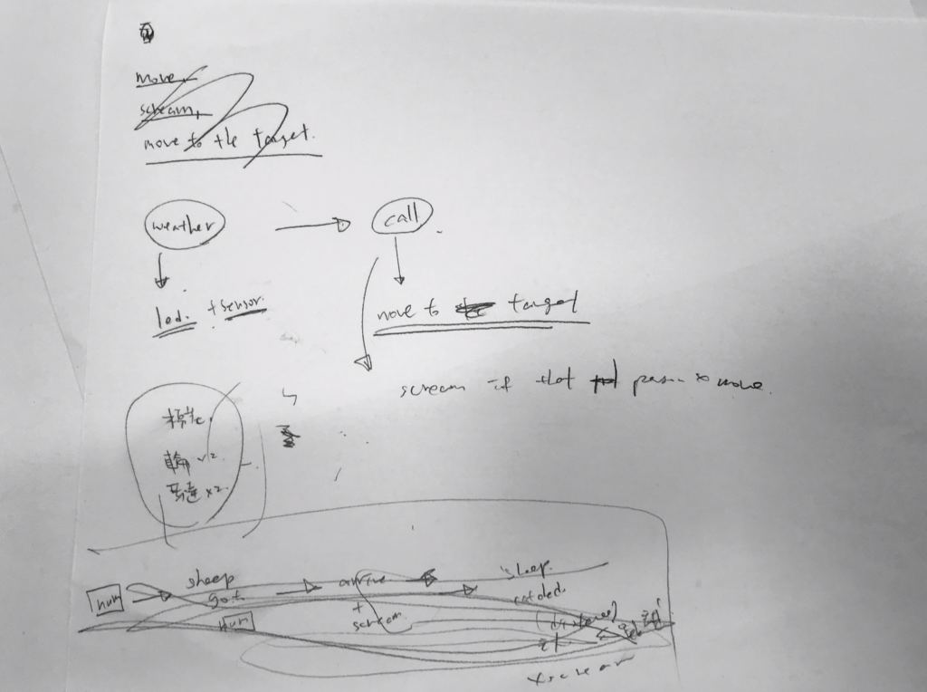
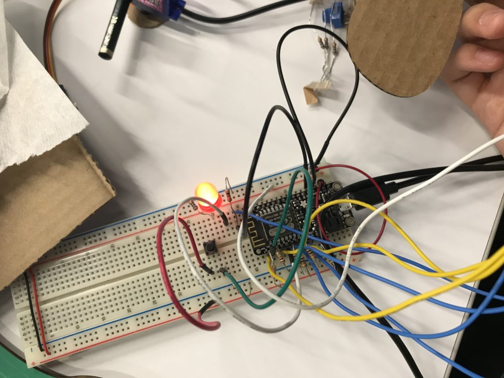
For my midterm project, I decided to switch my topic from temperamental sheep to “Teletubby.” Teletubby is an empathetic elf who cares and understands your inner feeling. At my draft attached below, in order to know how a person feels, I use the force sensor as input data in the beginning. Teletubby will be able to know your mental condition by analyzing the frequency and volume from your answering voice. However, I ended up using a force sensor because I think users could be more interactive with the device. 
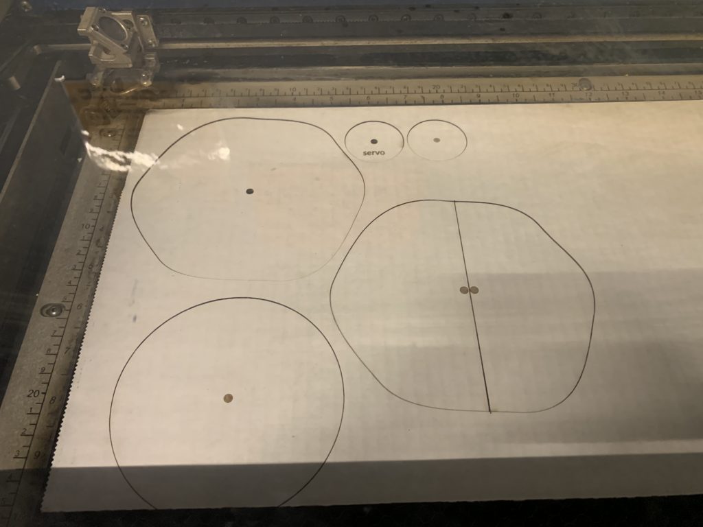
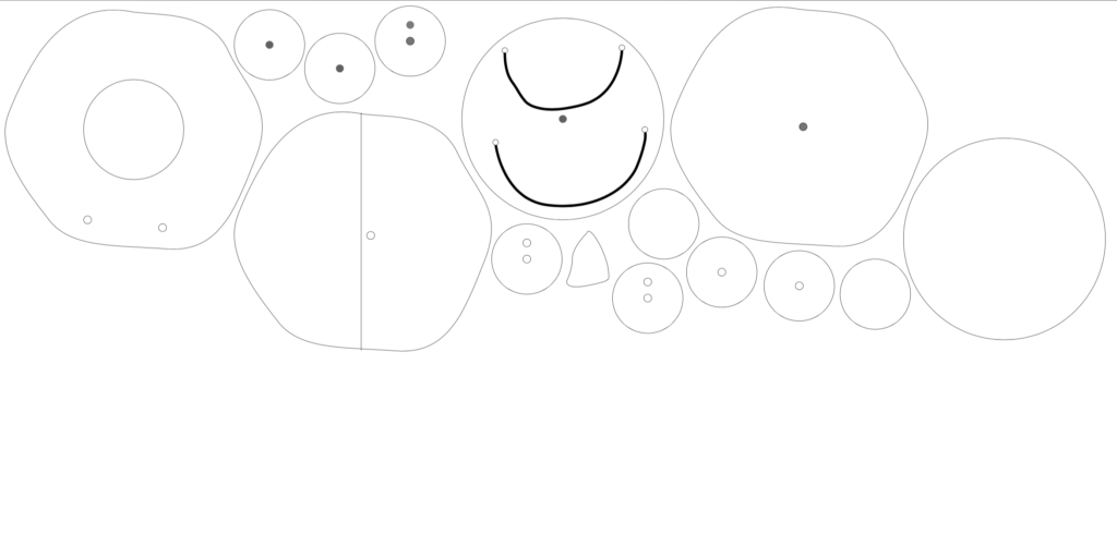
I began with creating an animation from p5.js, and linked it with arduino by using arest.

p5.js Draft
p5js

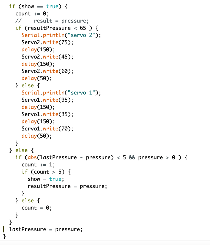
To start the interaction, people could input their stress level by pressing the force sensor, and the data will be mapped from 0 to 100, and people could see how much force they pressed by looking to the bar shown on the screen. If the force sensor has been held for a static level, within a range 5, for 3 seconds. In order to control the timing, I wrote a variable, count, and if the difference between data from the last loop and a new loop is smaller than 5, the count will be added one. 

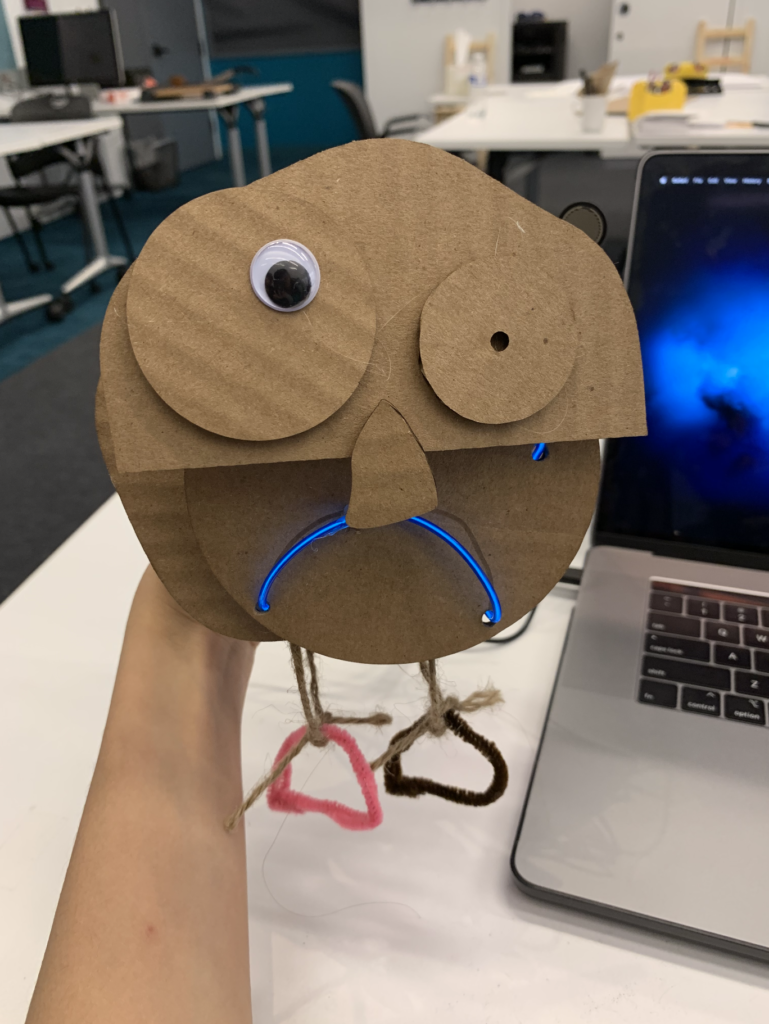
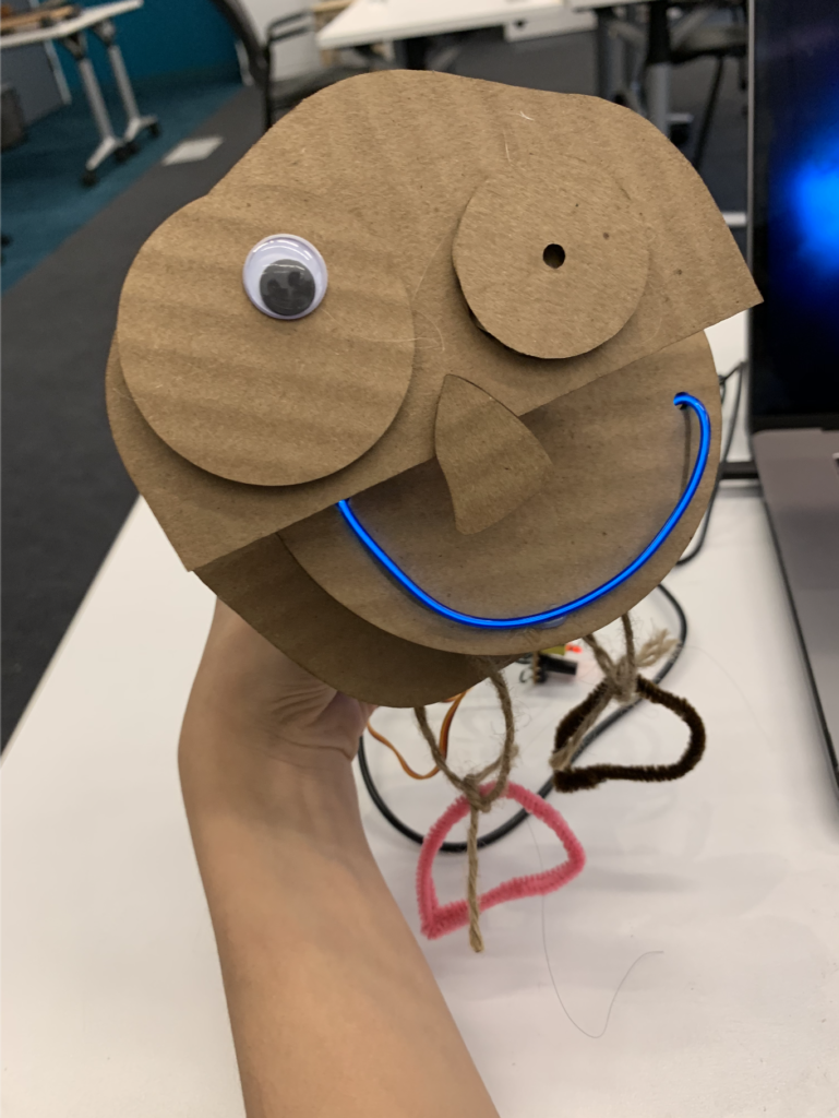
After Teletubby got your stress level, he will either smile and wiggle or showing a sad face depends on your condition. If your stress level is lower than 65, this means your at good condition, otherwise, you’re not feeling well, and he will make you feel his empathy by showing a sad face to you. 

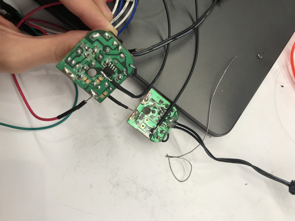
This is actually one of the difficulties I met. In order to have two facial expressions, I was intending to use two different EL wire, red and blue. The EL wire I bought is the one which needs to use two 1.5v battery and control different three lighting mode by clicking the button. In order to connect it with Huzzah and control by it, I solder three wires to make the circuit works. However, once I tried to use two EL wire at the same time, one of it will start blinking and the other one gets really dim, so I gave up using both. I ended up using only one EL wire and make it rotate by using a servo, but I forgot that the servo couldn’t be rotated up to 180 degrees. 

If I got more time on this project, the first thing I would do is solving the EL wire problem. I would try to figure out how to make two EL wire work simultaneously. After this, I’d like to add sound for Teletubby, so the user could have a stronger connection and interaction with him. Last but not least, I’d like to refine my prototype and come up with something people can really hang on their wall and play with him every day. 

Midterm _ TemperamentalSheep

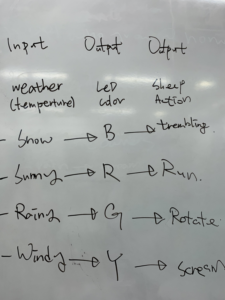
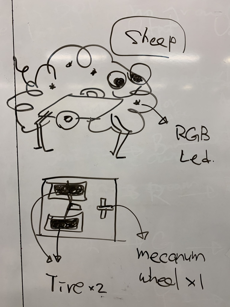
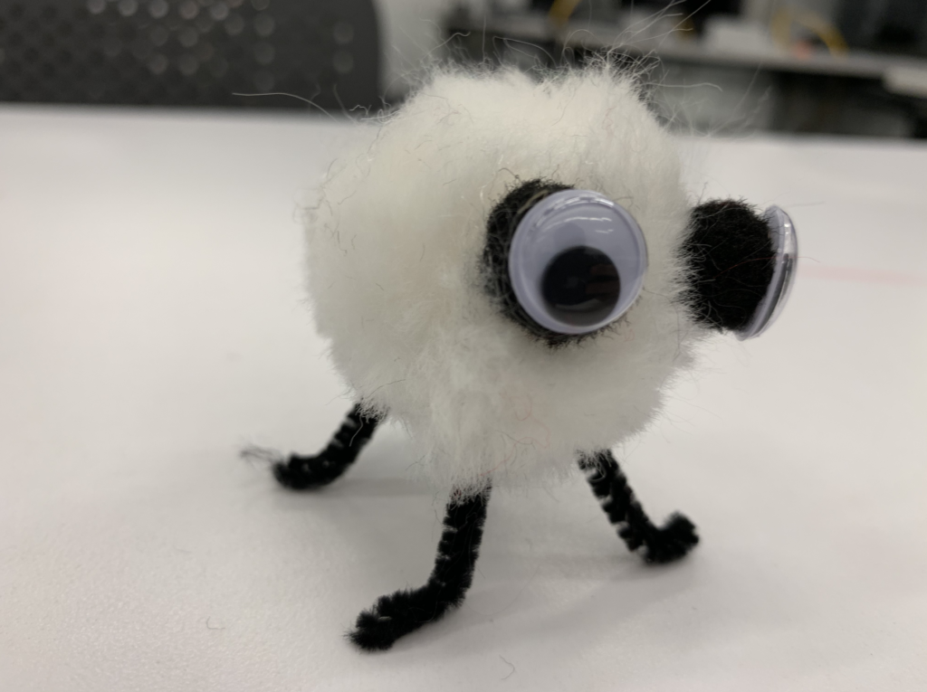
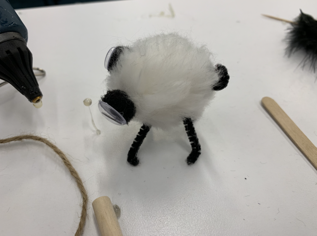
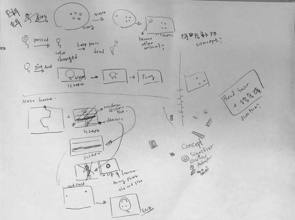
For my midterm project, I will be creating a temperamental sheep. It will be able to tell users the current weather by changing its color and behavior. 

As the attached photo shown, different weather condition corresponds to a different sheep’s behavior. In order to let the sheep move freely, I will be using two normal wheels and one mecanum wheel. As for the color changes, I will be using RGB LED light and hide them in the sheep’s cotton. However, if only using weather API as an input, it would be hard to see the difference between different weather condition. To demo it more easily, I will be using photoresistor as an input.

Hw4_WebServer_ControlledJumpingFish

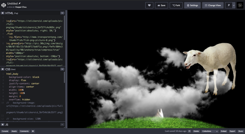
For this week homework, I decided to create an interactive animation. Users could control how high the fish jumps by adjusting the potentiometer.

I wrote the animation with HTML and CSS in Codepen before connect it with Huzzah. 

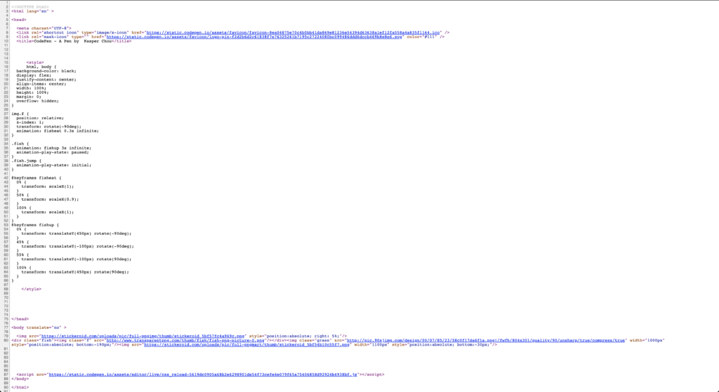
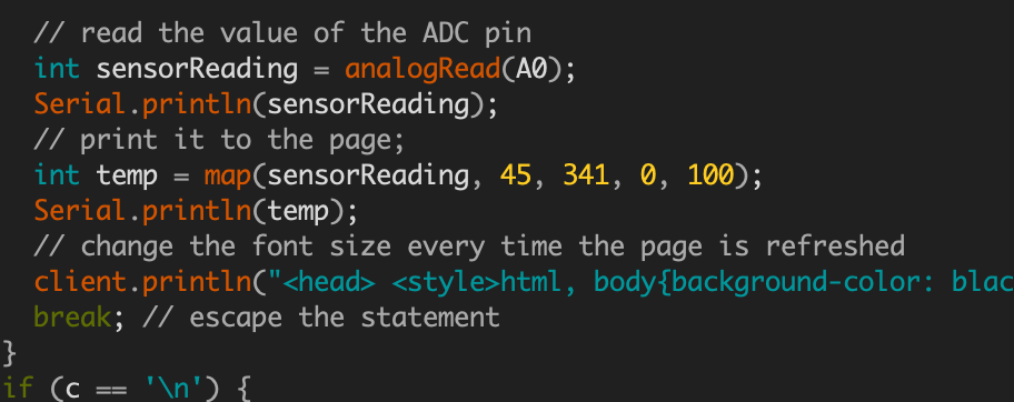
Due to the limit space of microcontroller, I minified my code before adding the into Arduino code. 

The larger of the mapped number of the potentiometer, the higher the sheep jumps. If the mapped number is less than 20, the fish will not start jumping into the air, and if the number is not high enough, the fish will keep rotating on the grass instead of leaving the grass.

HW3_LoveMachine_He Loves Me… or Not

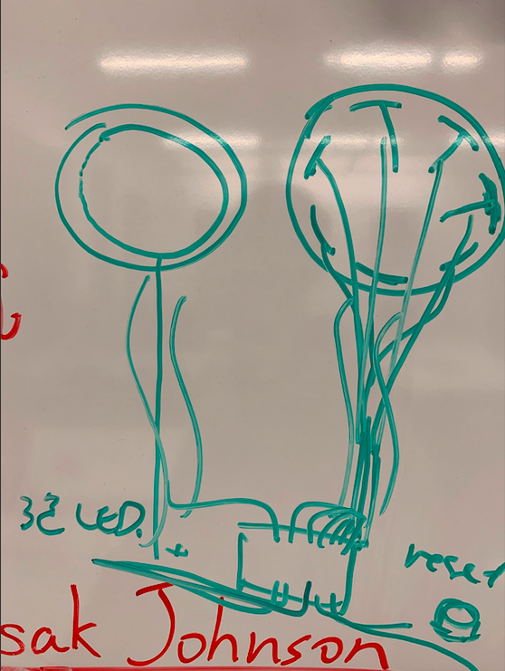
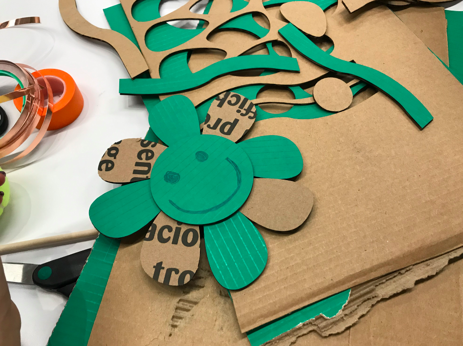
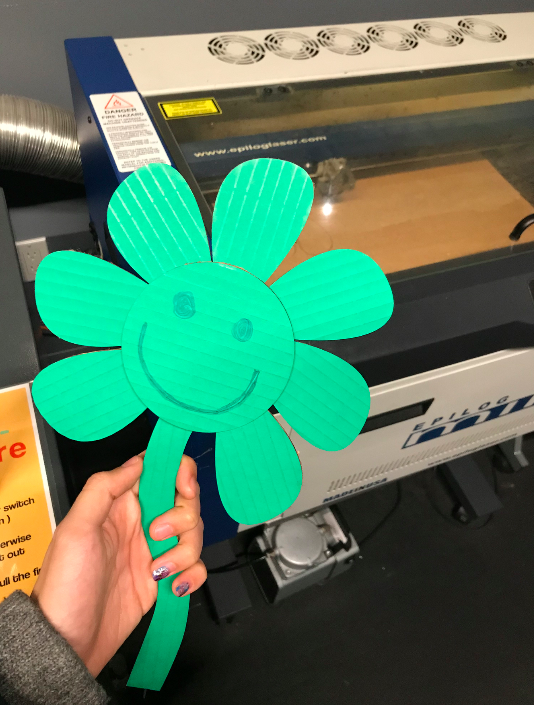
Che-Yu and I came up with an idea of using the fortune-telling game “He loves me, he loves me not” or “She loves me, she loves me not” to see whether or not you are compatible with your soulmate. In this game, one person will speak the phrases “He (or she) loves me,” and “He (or she) loves me not,” while picking one petal off a flower for each phrase. The phrase for the last picked petal represents the truth between the object of their affection returns that affection or not. 

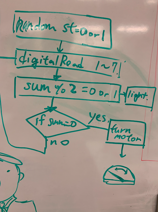
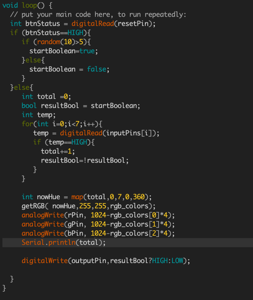
As for our love machine, the player will do the same as the game. While the seven petals are picked off, the color of RGB LED light will change from red to green to blue. In order to solve the issue that there will always be only seven petals and the player might have already known the outcome without picking off the petals, we set a random value for the beginning status. If the LED lights up in the end, it means you are compatible with your affection. If not, you could play the game over and over game until you reach your ideal outcomes!

Code

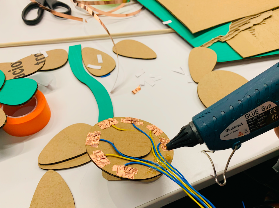
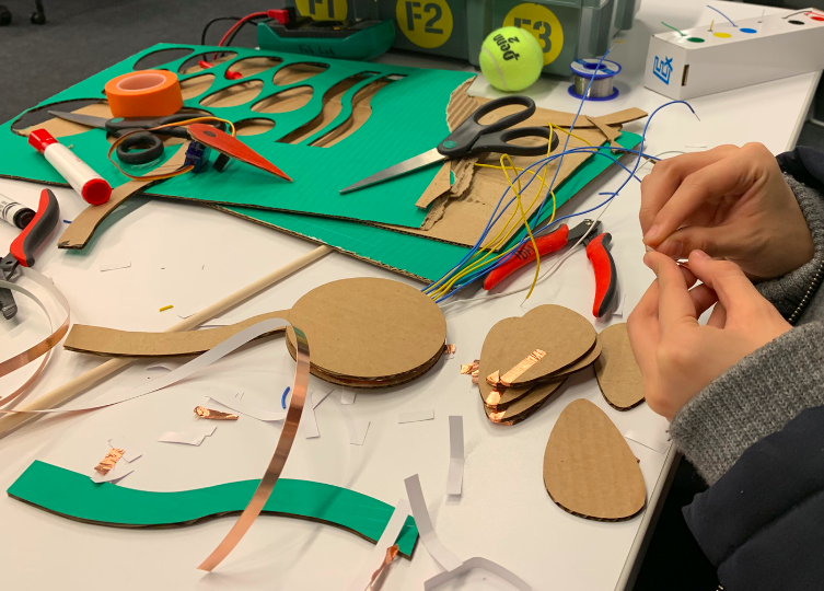
However, we don’t have any testing video at this point, because we have failed to make the entire flower conductive. We use mainly cardboard and copper tape for both prototype and the final version. As we were testing each petal’s conductibility, not every petals work. Instead, only two of them works well. We tried to add more conductive layer to the attached surface to make the rest petals conductible , but it didn’t work as we thought. So our next step will be finding out the conductive problem, solve it, and make this game happen with our love machine.

(Update Feb. 22)

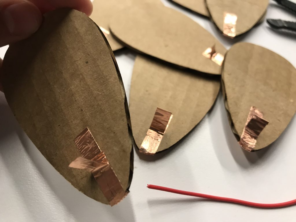
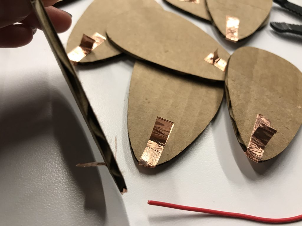
In order to solve the conductive issue, we folded copper tape into a special shape and sticked it on each petal. As you can see in the attached photo, the attachable surface becomes wider and thicker. 

Observation

Last Friday, I was observing a student trying to compose sound effect by using serge synthesizer and oscilloscope in IDM audio lab. Serge synthesizer is an analogue module synthesizer and oscilloscope is a laboratory instrument used to display and analyze the waveform of electronic signal. In order to create sound effect, the student has to connect the audio signal and control voltage jack via banana cables. At the beginning, he started with plugging in banana cables to the speaker output. After making some basic sound effect, he started to add more cables and adjust other cables in order to create more variables and achieving the ideal sound. The intriguing part is that there are six different colors for the cables, and each color has a specific length. During the observing process, despite the time he used for listening the sound and wondering about how to adjust it, most of the time he is switching the cable to the one with the suitable length and finding where to plug in. Nonetheless, I noticed that sockets on the synthesizer has four different color, each color for a different function. The red one is for control, purple for sync, etc. This efficiently shorten the student’s time for finding which is the appropriate socket to plug in. After all, this machine seems complicated to me, but actually it possesses a special module arrangement and color differentiation to simplify it’s interface.