Radio Controller

Hello!

This is my final video showing the eleven working buttons:

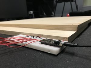
And here are some images that document my development process:

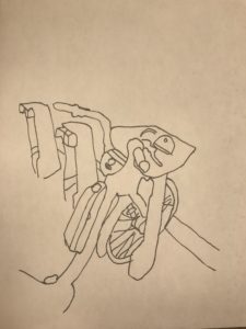
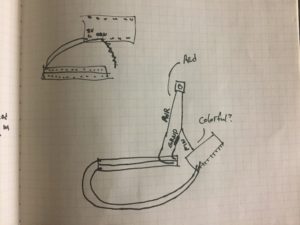
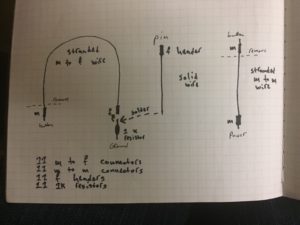
some little drawings I made while first attempting to visualize the network inside of the radio:

once I generally figured out where things needed to be, I sketched out various components so that I could streamline them–this is the GND end of each button:

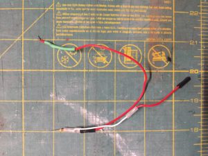
one of my first attempts at making a said GND component:

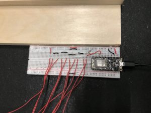
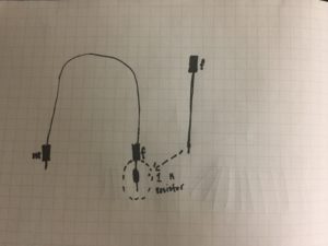
I then sketched out exactly what I would need to connect all eleven pins on the microcontroller to all eleven buttons on the motherboard. I later used this sketch to figure out what supplies I needed. I ended up not using the female headers because I could never get them to work quite as well as premade, already-connected female headers on m to f connectors–I often cut off the female ends of m to f connectors and used those instead:

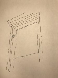
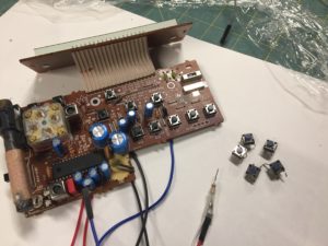
I began prepping the inside of the radio and wanted to get as much room as possible, so I removed the radio’s glued-in speaker (among other things):

I then began experimenting with soldering onto the motherboard. I couldn’t figure out how to solder onto it well–in part because the solders in the Fab Lab suck, in part because I was using solder that was too thick–and Scott did this demonstration, which I then used as a model:

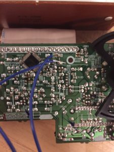
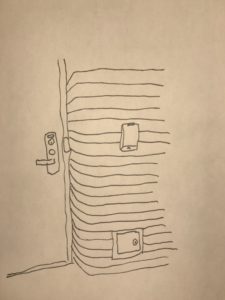
after soldering a few wires onto the motherboard, I realized that the preexisting buttons simply weren’t reliable, and especially weren’t reliable when multiple were connected to the same power and ground. so I went through and replaced the buttons with newer, more reliable ones.

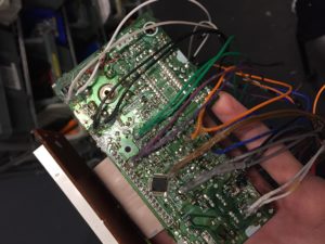
after a lot of work, I figured out the interior logic of the motherboard and arranged all of my powers and grounds so that there would be no shorts. I color coded the buttons so that I could keep track of their wires and then hot glued all of the soldered connections to protect and strengthen them:

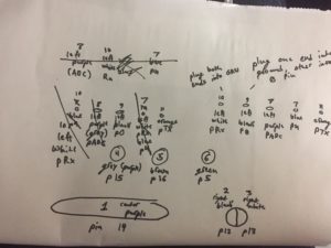
here’s my final master-key, although it’s probably pretty unintelligible. I used this to keep track of the radio’s external buttons and their respective 1) “button number” 2) wire color 3) pin on the microcontroller. I used the button number to organize the buttons in Unreal Engine. This was super necessary and helpful:

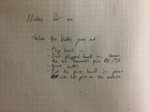
and here are some final notes that I needed to write down for when I come back to this controller and don’t understand why it isn’t working. It primarily has to do with the RX and TX pins:


All in all, I’m really happy with this controller. I’m also happy to say that my controller was actually fully functional when I displayed it in class–I’m pretty sure the clock wasn’t showing up because of how widgets are displayed in UE4 on differently sized windows, and the window size had changed when my computer went into projection mode, and I’m pretty sure that the bloom button wasn’t responding because I’d screwed the back of the radio on too tight and the button was being continuously pressed down. When I went back to my dorm and tried it, everything was working fine. I’m genuinely proud of this project, it’s actually really cool, and I honestly want to make it again except better, knowing what I now know.

Some potential improvements for a later version:

  • Using the other bits and nobs on the radio
  • Minimizing the amount of space taken up by wires
  • Finding a microcontroller with more normal digital in/out pins–the RX/TX pins aren’t sustainable for a final version of this project
  • Making it all fit nearly into the radio so that every button feels the same when pushed down
  • Figuring out a recharging system that doesn’t require me to open up the radio, but that is also still discreet enough to make the radio look and feel wireless
  • Cleaner, better planned out relationships between the buttons on the motherboard and the pins that they’re connected to


Final update

Here’s the Max Patch that I’ve started working on as it’s communicating with Unreal Engine:

As of now, my breadboard isn’t yet communicating with Max wirelessly. Once I do that, I’ve finished this portion of the project.

I’ll likely find 1/2 more old electronic things. Then I need to figure out + order the small wireless microchips that I’m going to put into each makeshift controller.

Final Proposal

This hot new video says it all!!! Also, I called this video a “midterm proposal,” which it definitively is not. This is a proposal for my final project.


More of Julian’s belated homework!

This is more of my belated homework!!

I talked a bit about this in class, but the network-based artwork I’d like to respond to is Raul Altosaar’s A Very Real Looper. We watched a bit of his video in class but I’ve linked it below just in case:

I think Raul made his piece work by taking the coordinates of his Vive controllers, mapping them onto a replica of that space in a three-dimensional digital environment, and then activating certain sounds when the Vive controller passed over trigger areas. I wouldn’t change anything about this because I think it does VR-ish musical performance well.

It might be worth saying that Raul didn’t make the networked devices that allowed his work to function; rather, he took the standard Vive controllers and found a new application for them. Somewhat similarly, I’d like to start my final project with preexisting devices. But I’d also like to go a bit further and repurpose these electronics, such that they are given a completely new function.

Julian’s Belated Drawing Homework

I did it!

I looked for three pieces of technology that put network infrastructure toward different ends. The first thing I ended up drawing is a CityBike, which presumably communicates with some sort of network via the device on the frame of the bike; this is a lovely use of networks because, at least in theory, it makes the bike more accessible, and bikes are probably the best form of sustainable transportation. The second is a security camera outside someone’s window, which is a bad use of networks. It might be the building’s camera, it might be the city’s, or it might be the person who lives in that room–in any case, I think it’s invasive to point that camera toward normal people on the street who just happen to be walking by. And the third is a touch-sensitive identification card reader, which is a less black-and-white use of networks. My initial impression is that this card reader is fun but unnecessary–because why not just use normal keys–and my second impression is that the card reader might better align with the security camera because the card reader can similarly be used to track those who use it. This is a less publicly invasive use of networks than that of the security camera, but it’s still kinda gross.

True Relaxation Fulfillment Incredible The Workplace Efficiency Maximization Tool Of The Future

Heyo! The two videos + images do quite a bit of explaining, so I’ll let those do most of the talking.

After recording the first video I changed my code such that the page refreshes more when the buttons aren’t pressed and refreshes less once they’re all held down.

I still was unable to get my battery working, which sucks; also the auto-play turned back off, and this time it was for seemingly no reason. I’ve tried everything I can think of, but hopefully I can get it working by tomorrow morning.

Overall I’m pretty happy with the execution of this project. It’s clear in its intent and the final thing is almost exactly how I’d originally envisioned it, sans timer function on the computer. I did a bunch of stuff I’d never done before–particularly with html, which I’m kind of proud of–and I feel good about the amount of time and energy I put into this project. Last but certainly not least, I’m so glad I could finally make something useful, and if anyone has any leads on local businesses that might be interested in trying this tried and true workplace efficiency maximization appliance, please do let me know.

Thank you for you time,

Julian Otis

NYU Class of 2021