Final Project:Wireless Color Sensor

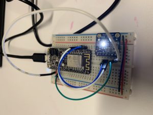
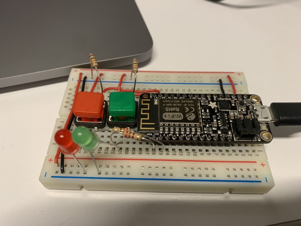
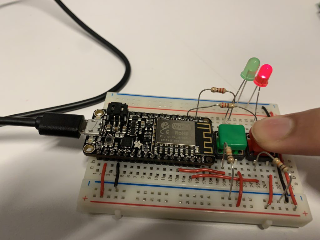
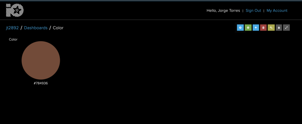
For my final project, I built a color sensor that would send the color information out to be accessed through a Adafruit.IO dashboard. The microcontroller is connected to TCS34725 RGB color sensor. The sensor collects the RGB value of whatever is put in front of it and that is then relayed to the microcontroller and then to the dashboard.

Initially, I wanted to build something that would use a phone’s camera to detect the color of an object. But after Professor Scott sent me the link to the color sensor, I was able to see the vast amount of resources for the sensor from Adafruit. Working with the sensor was cumbersome, even with these resources. There was a lot of “figuring out” how to use the sensor initially. One of the major problems I had was figuring out how to send all the data as the correct data type to Adafruit.IO in order to use the dashboard. Next steps for this project would be to build out the physical interface part. I used a small box to store the circuit, but I would like to build a proper enclosure and connect a battery so the circuit could be taken on the go. Another iteration would also include a way to store the color information more easily. At this time, the color information is shown on the dashboard but changes every 3 seconds.
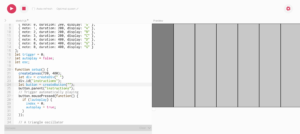


[code]
#include "config.h"
#include <Wire.h>
#include "Adafruit_TCS34725.h"


// default PWM pins for ESP8266.
// you should change these to match PWM pins on other platforms.
#define RED_PIN   4
#define GREEN_PIN 5
#define BLUE_PIN  2

// set up the 'color' feed
AdafruitIO_Feed *color = io.feed("color");
Adafruit_TCS34725 tcs = Adafruit_TCS34725(TCS34725_INTEGRATIONTIME_50MS, TCS34725_GAIN_4X);

void setup() {

  // start the serial connection
  Serial.begin(115200);

  // wait for serial monitor to open


  // connect to io.adafruit.com
  Serial.print("Connecting to Adafruit IO");
  io.connect();

  // set up a message handler for the 'color' feed.
  // the handleMessage function (defined below)
  // will be called whenever a message is
  // received from adafruit io.
  //color->onMessage(handleMessage);

  // wait for a connection
  while(io.status() < AIO_CONNECTED) {
    Serial.print(".");
    delay(500);
    

  }
      if (tcs.begin()) {
    Serial.println("Found sensor");
  } else {
    Serial.println("No TCS34725 found ... check your connections");
    while (1); // halt!
  }

  // we are connected
  Serial.println();
  Serial.println(io.statusText());
  color->get();

  // set analogWrite range for ESP8266
  #ifdef ESP8266
    analogWriteRange(255);
  #endif

}

void loop() {
  
  // io.run(); is required for all sketches.
  // it should always be present at the top of your loop
  // function. it keeps the client connected to
  // io.adafruit.com, and processes any incoming data.
  float red, green, blue;
  
 // tcs.setInterrupt(false);  // turn on LED

  delay(3000);  // takes 50ms to read

  tcs.getRGB(&red, &green, &blue);
  
  tcs.setInterrupt(true);  // turn off LED

  //Serial.print("R:\t"); Serial.print(int(red)); 
  //Serial.print("\tG:\t"); Serial.print(int(green)); 
  //Serial.print("\tB:\t"); Serial.print(int(blue));

Serial.print("\t");
String hexi;
hexi = ((String((int)red, HEX)) + (String((int)green, HEX)) + (String((int)blue, HEX)));

//Serial.print("This is sexy:\t"); Serial.print("#"+hexi);
    Serial.print("\n");
  Serial.print("sending -> ");
  color->save("#"+ hexi);

}

// this function is called whenever a 'color' message
// is received from Adafruit IO. it was attached to
// the color feed in the setup() function above.
//void handleMessage(AdafruitIO_Data *data) {
//
//  // print RGB values and hex value
//  Serial.println("Received:");
//  Serial.print("  - R: ");
//  Serial.println(data->toRed());
//  Serial.print("  - G: ");
//  Serial.println(data->toGreen());
//  Serial.print("  - B: ");
//  Serial.println(data->toBlue());
//  Serial.print("  - HEX: ");
//  Serial.println(data->value());

//}
[/code]

Final Project Update

For my final, I’ve bought the TCS34725 sensor that detects the RGB value of whatever is put in front of it. The microcontroller then outputs the RGB value to the serial monitor, allowing you to see in real-time what the sensor is seeing. Now I am working on connecting the values to a GPU that would allow the user to see what color is being put in front of the sensor. 

light_Capture.jpg

Final Project Proposal

For my final project, I want to develop a way to take pictures, recognize the colors in that picture, and be able to display the color information to the user. This would be used for designers who see inspiration in the outside world or people who are color blind and need to identify a color. I would want to use a camera that is linked to another device using MQTT that would process and display the color information back to the user. For the camera, I could use a camera that would connect to the microcontroller then use a color recognition API to receive the color information and possibly send the information to a mobile device or another online service.

Meme Messenger

Using MQTT, I’ve created a way to send your favorite meme(s) to yourself at a moment’s notice.

I used IFTTT to link a button which was wired to the microcontroller to Facebook Messenger. After the button is pressed, an image would be sent to your Facebook Messenger account. I initially hope to find a way to randomize the image being sent, and even tried to incorporate the Giphy API, but I couldn’t get it to work. Instead, the meme that is sent reflects how I felt when working with the API.

Network Infrastructure

For the first piece of network infrastructure, I noticed a large white box on the roof of my apartment building early in the week. After checking Ingrid Burrington’s guide, I learned it could have been a microwave antenna, due to its cylindrical shape, which would be providing internet service to the building. The antenna likely connects to another antenna and provides for the tenants of the building below.

The next device is an NYPD security camera, which was located on an intersection in downtown Manhattan. The device had two cameras and a medium sized antenna attached at the top. The device most likely transmits a live feed of whatever the cameras are recording using the antenna. As for the internals, the device probably has components for transmission as well as storage for backup recordings. It exists this way in order to record and watch the streets.

The third and final device is a red light camera I observed in Queens after a few cars ran the light and its camera started to flash. This device detects when a car has crossed the intersection during a red light and then takes a picture of the car in order to identify its license plate. It exists in this form because it needs to be higher up in order to have a vantage point of the intersection, the car, and its license plate. The box is most likely wired through the pole to an external device.

Midterm Project: Piano

For my midterm project, I wanted to make a piano using a p5js sketch, the aRest library, and physical buttons in order to control the p5 sketch. Curtis and I had difficulties while working through the project. We wanted to just aRest but we couldn’t retrieve the IP address of the microcontroller in order to set up our p5 sketch. Our problems were on the software side of the project and before the next class, I hope to finish this midterm project completely using the aforementioned methods. Below is a picture of our project, which I would want to improve with more work.

Midterm Write-up

For our midterm project, Curtis and I are making a piano that we can control with the microcontroller. Our webpage would have piano keys that would emit a sound when the corresponding physical button is pressed on our circuit. For our webpage, we are using p5js for the piano’s functionality.

Each button in our circuit would be matched up with the corresponding key on the  p5 sketch and, in turn, play a sound. For our project, we still need to implement the physical inputs in our p5 sketch. We also want to find a better way for the user to press the keys that isn’t small buttons as well as polish our user interface that will be displayed on the screen. If we have time, we may implement a way for the users to be able to loop sounds within our user interface.

Love Machine

For my love machine, I wanted to emulate the swiping mechanic from dating apps into a button system. I wanted a way of matching people by accepting or rejecting them using green and red switches and LEDs. I programmed the microcontroller with two colored switches that are connected to their respective color of LED. If you press the green button, then the green LED would turn on. If you press the red button, the red LED will turn on. Instead of using simple switches, I opted to use the colored one so anyone using the circuit would know which button to use in order to activate the correct LED. This idea came from the Prepared Brain idea from “Attractive Things Work Better” where the brain naturally assoicates things such as color.

Observation Assignment

In class the other day, I was observing my professor interact with the touchscreen interface for the projector. They were trying to change the output of the projector to their laptop but were having a difficult time changing the input. The touchscreen panel was small, about 8 inches by 5 inches with icons for each of the outputs. They would constantly press the buttons on the touchscreen and after a minute, the touchscreen interface performed every delayed action almost simultaneously and finally displayed her laptop. I think the touchscreen allows for more errors when compared to physical buttons due to the need for feedback from the touchscreen. Another observation I made was of a girl trying to use her laptop when it suddenly froze. For the first minute, she tried clicking using her trackpad, swiping and performing touch gestures, and conducting keyboard commands. Following this, she back away from the laptop and eventually, she was able to continue on whatever she was doing. The main barrier she encountered was not being able to access anything on her laptop through any of the controls given to her.

Hands-free switch

For this assignment, I decided to make a switch with uses your body to close a circuit. The circuit consists of an LED, with two transistors, and a power source. The LED’s power comes from two transistors which are only connected to the power source when the circuit is complete using your body as your body acts like a wire between them.

I demonstrated with my arm, but it could be done with any part of the body.

Below is the website I used to make the circuit:

http://www.mallinson-electrical.com/touch-switch-circuit

Update: This week, I tried to make my switch using the microcontroller. I couldn’t get the circuit to work with the two transistors or using the body as the conductor so I opted to use salt water as my switch.

The salt water was able to complete the circuit and act as a switch for it. I decided to implement the salt water as it was recommended by the link I used above for last week’s circuit.