For my final project, I decided that I should make something that would solve an actual problem in my life. I have never been a morning person, and most alarm clocks I’ve used haven’t been particularly good at getting me to actually wake up. My old clock radio, though I do appreciate its projector feature letting me check the time without moving in bed at night, is too quiet, and my phone is too distracting once i’m even slightly awake, and sometimes I forget to charge it and it doesn’t wake me up at all. So I went with an old-school solution: An analog alarm clock. This one to be exact.

It was definitely loud enough, and it was small enough to put basically anywhere in my room. This meant I could put it somewhere I’d actually have to get out of bed to turn it off. But it too had a problem. The alarm time setting was rather imprecise, relying on an extra hand that pointed at the time you wanted, so you were basically guessing at what exact minute you wanted to wake up. Sometimes it was off by more than half an hour, which was quite annoying.
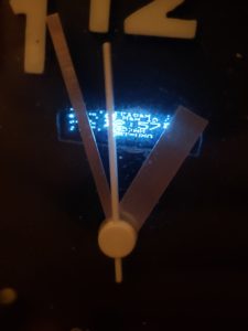
About a year ago, I decided that it was still a bit too easy to turn off so I added a key switch in parallel with the original alarm switch, and kept the keys in the bathroom. This meant that I had to leave my bedroom to shut my alarm off, but it also meant that it’d be ringing nonstop until I did, which my mother did not appreciate at all. The cheap key switch I also used also had the little problem of not actually requiring the key at all. You can turn it with just about anything thin enough to fit into the keyhole. I guess you get what you pay for. Anyway, enough about the past. Let’s talk about the present. This is what the alarm clock looks like now.
[pic of working clock]
I originally wanted to go with a sort of retro-futuristic clock face with two rings of LEDs, 12 for the hours on the inside and 60 for the minutes on the outside, and maybe a nice OLED display in the center, but that wouldn’t work for a few reasons. My first thought was to use WS2812 addressable LEDs, also known as Neopixels, but a ring of 60 of those is far too large to fit in the clock face I have, and would also be quite expensive. I also thought of just building an array of 72 regular LEDs, but the circuitry to drive all of those would be very complicated and probably tie up most of the pins on the microcontroller, so I went with plan C: Keep the original clock movement intact, but integrate a small OLED into the face an
d rewire the alarm motor to turn on when commanded by the microcontroller.

Building the hardware was probably the best part of this project for me. I enjoy taking an idea out of my head and turning it into something I can hold in my hands. I started by wiring up the OLED display to my microcontroller and running the Adafruit test sketch to make sure it all worked. Once that was all set up, I got to work disassembling the alarm clock and making a hole for the display to be visible through. This was a lot more difficult than I expected, as the clock face was about 4mm thick and made of very tough plastic. I ended up having to drill a few holes and then cut out the space between them with pliers before I could fit a file in there to get the hole to be the right size and shape. After that was done I made a power-distribution board out of a solder prototyping board to connect power and ground to the various parts. I used a DC-DC step-down converter to change the 3.3v from the microcontroller to the 1.5v the original clock movement and motor ran on, and I used a small transistor to switch the power going to the motor. Once all of that was wired up all that was left hardware-wise was to secure the screen with a bit of hot glue and close up the back, and then came the difficult part: getting the software to work.

Dealing with time and time zones can be a bit of a headache, and I’ve never been a particularly skilled programmer, so I quickly decided that writing my own clock software completely from scratch was out of the question and went looking for an open-source implementation I could modify to suit my needs, and I found it here. It wasn’t exactly what I needed, but it made a good foundation to start with. The alarm function worked perfectly , but the display only sort of worked, you could kind of make out the time but it was formatted for a different aspect ratio display and it came out mostly garbled. It took a bit of digging through the Adafruit I2c OLED display library but I eventually figured out how to make it work and cleaned up the text, removing the date, day of week, and seconds to make room for a clearer, more easily readable time display to set the analog clock to. After that, I decided to add a few more buttons to the web interface, because the original one only had the option to increase or decrease the alarm one minute at a time, which was a nightmare to use on my slow, unreliable WiFi. I added +5 and +30 minute options and that streamlined things greatly.
My modified code can be found HERE
Overall, I’d consider this project a success. It sets the time automatically over NTP and it did manage to wake me up every morning I tested it on, though there are a few things I’d like to add. I want to re-implement the key switch function at some point so it really forces me out of bed, hopefully with a slightly higher quality switch this time around. I also figured out a really easy way to reverse the polarity on the battery connectors the ESP8266 Huzzah board uses, as the ones I bought came backwards. You just have to lift up a little plastic tab with an x-acto knife and pull each wire out. You can then pop them back in in the correct polarity for your microcontroller. The batteries I bought don’t have enough capacity to run the clock for more than a few hours, but they’d be enough for if the power went out for a couple of hours or if a cat, dog, or small human accidentally knocked out the USB power supply during the night.


