Final Project: Temp Cup

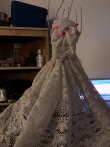
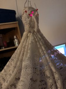
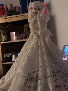
The basic idea of this project was to create a coffee cup handle that measures the temperature of the cup it is holding. But it evolved into a tracker of your drinks according to the temperature. The end up product looked like this:

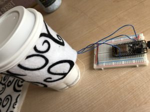
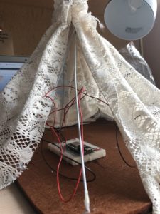
The temperature sensor, the LM35 sensor, was sewed behind the felt cover on plain fabric and this fabric was sewn on to the black and white felt cover. The wires were soldered to the ports of the sensor because sewing it with the conductive wire fell apart. This then attaches to the microcontroller.

To set the reminders, the triggers were set up in the If This Then That app on my phone, and the two triggers looked like this:

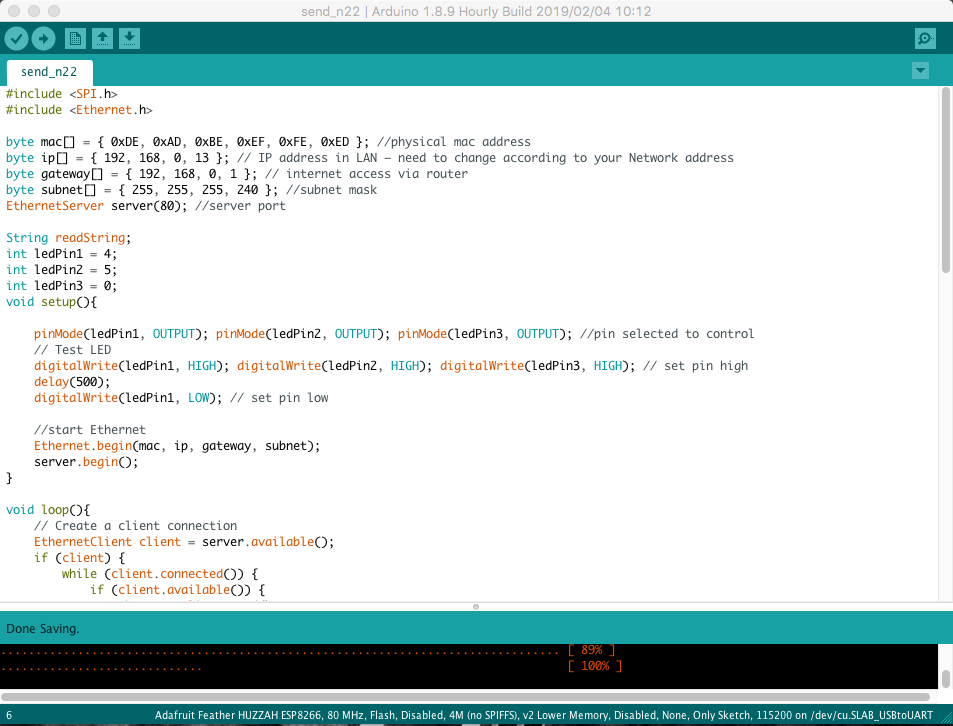
For the monitor in Adafruit, I set up a temperature block that monitored the live temperature feed every time I am operating the microchip. For the code, I used a simple temperature measuring code from the library.

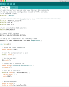
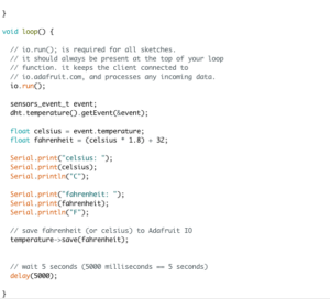
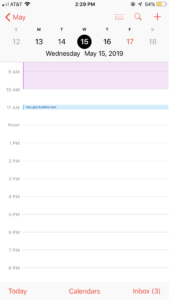
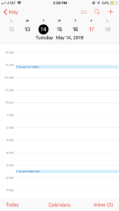
After setting up the Adafruit key and connecting it, I started running the programme before every time I got a hot or cold drink and my calendar sort of ended up looking like this.


This was only for a week, but if extended, this can go on for more time. One of the important problems associated with this was the fact that I had to switch it on before every time I got a drink. If there was any way of making it automatic, I would actually consider it as a viable product since I really do need to control my bubble tea and caffeine expenses. Sometimes, the sensor wouldn’t read the temperature properly, so I had to press it against the drink and then remove the cup sleeve after it read the value and switch it off so it didn’t take too many readings and add too many events to the calendar. Below are two example days which had a reminder on my phone. The shortest amount of time was a duration of five minutes, so that’s what I set it as.

Overall, I was pretty proud of this project because I knew exactly what needed to be done and how I had to do it for all the steps, unlike my midterm project which was a little more than I could handle. If I could, I would probably try and search for more ways to make this process more automatic, but I wasn’t sure how. That would give me a cup sleeve that thinks on its own, telling you when to stop slowing down on drinks, because you have spent way too much money on bubble tea!.

Final Project Proposal

Something that I’ve stumbled across on Pinterest in my avid browsing for cute aesthetic DIY things I will never make are cup holders that looks sort of like this.

24 Creative Christmas Fabric Crafts - Captain Decor(from Pinterest)

So I was planning to use soft circuits that we learned about last week to sew in a soft circuit along with a temperature measuring device from Adafruit (i still have to decide which one) and make a cup holder/sleeve that would send a text message to your phone if the cup is hot or cold. The sleeve would have two layers: a cloth inside that has the circuit sewed on to it and a slightly harder and prettier outer layer to cover the ugly circuit. If possible, this would have a bottom that will contain the microcontroller hidden in the bottom. To connect it, i might have a web page that would connect to the sleeve simultaneously that would do the same thing the text messages does. Hopefully, this cool cup holder would touch upon the useless DIY stuff of the internet world that people comment on how pretty it is, but will obviously never do it themselves.

Infrastructure in the City

When I was asked to wander around to look for internet infrastructure, one of the first things I came across was the Metro card refill station, where I had to refill my metro card with my credit card. In these stations that are located in almost every subway station across the city, uses the EMV chip of the credit card to make transactions. Therefore, the machine needs to remain online to send a cryptogram to the card provider, who authorizes and authenticates the card or denies the transaction according to the bank account information of the user.

One other pretty large thing I noticed was the billboard that is located (for aesthetic purposes) at Times Square (but in reality, everywhere). These large LEDs are connected and wired to the internet. Even if they could not be hacked, their images are programmed online and then set. The picture below is one of the billboards I saw in Times Square.

Another device that can be connected to the internet is the thermostat. Below is a picture of our dorm thermostat. Some smart thermostats can be controlled with apps and are therefore connected to the internet as a device. Our model is, sadly, not a smart thermostat, but there were talks amongst the RAs and building administrators to connect it to our phones since our current thermostat keeps on malfunctioning.

Midterm Project – Light-Up Dress (IP aDRESS)

Something I have always wanted to know more about was wearable technology, and once I had to finalize something for my midterm project, I decided to try making a mood dress where different colour LEDs would light up when the button was pressed on the website it was connected to. But since I faced a bunch of problems, I dumbed it down to a much simpler form with six LEDs in total.

This is what the model “dress” looked like without any of the wirings.

The bracket (not shown) was made of thin wire hangers cut and stuck to a brown foam base with a glue gun. They were brought to a sort-of humanoid shape with thread (both the glue and solder weren’t sticking) and the white lacey cloth was strung together in two parts: the top bust (stitched) and the bottom skirt (pleated and stitched) and were attached to the bracket with more thread and some glue.

Next, the wiring was done. I tried setting up multiple colour LEDs, but it wouldn’t work with more than one LED in series for the yellow or green colour, so I stuck with the red. According to the current reading, only two of the red LEDs could be added to a single output pin. This is what the wirings looked from inside and the LEDs look like attached from inside to the dress.

One thing I had really wanted to do was add the LEDs in a particular pattern so that they look neater when lighting up, but because of the mess inside the dress with the wires, I couldn’t insert the LEDs to the pattern I wanted it to be in.

For the code, I used the Ethernet shield over the Serial Peripheral Interface rather than the aREST library because I thought it was easier. This is a section of the code.

After being set up, these were the three settings of the led that lit up. Since there was only one colour LED that I could use, I thought of using sections rather than colour.

After this project was over, I realized there were many aspects to it I would like to improve later on if I had more time, like the overall look of the model, the number of LEDs, and even work on different patterns with the different lights and maybe incorporate other colour LEDs by removing them from series to match up the current.