Final Project: Connected Analog Alarm Clock

For my final project, I decided that I should make something that would solve an actual problem in my life. I have never been a morning person, and most alarm clocks I’ve used haven’t been particularly good at getting me to actually wake up. My old clock radio, though I do appreciate its projector feature letting me check the time without moving in bed at night, is too quiet, and my phone is too distracting once i’m even slightly awake, and sometimes I forget to charge it and it doesn’t wake me up at all. So I went with an old-school solution: An analog alarm clock. This one to be exact.


It was definitely loud enough, and it was small enough to put basically anywhere in my room. This meant I could put it somewhere I’d actually have to get out of bed to turn it off. But it too had a problem. The alarm time setting was rather imprecise, relying on an extra hand that pointed at the time you wanted, so you were basically guessing at what exact minute you wanted to wake up. Sometimes it was off by more than half an hour, which was quite annoying.

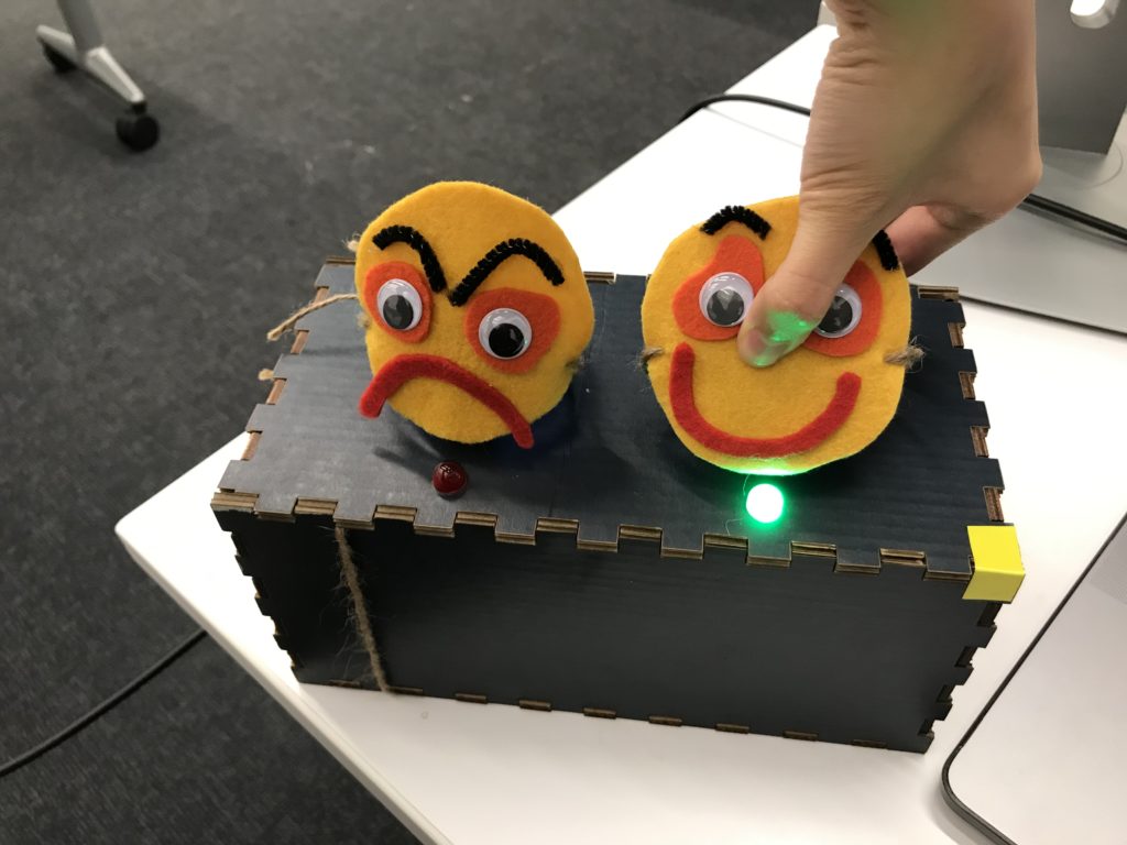
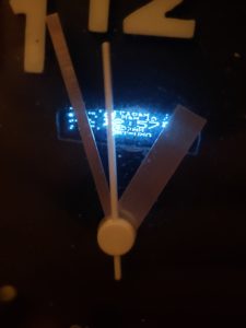
About a year ago, I decided that it was still a bit too easy to turn off so I added a key switch in parallel with the original alarm switch, and kept the keys in the bathroom. This meant that I had to leave my bedroom to shut my alarm off, but it also meant that it’d be ringing nonstop until I did, which my mother did not appreciate at all. The cheap key switch I also used also had the little problem of not actually requiring the key at all. You can turn it with just about anything thin enough to fit into the keyhole. I guess you get what you pay for. Anyway, enough about the past. Let’s talk about the present. This is what the alarm clock looks like now.

[pic of working clock]

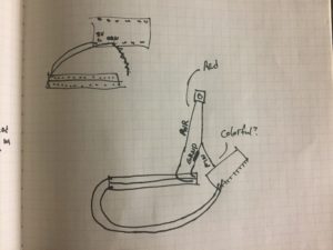
I originally wanted to go with a sort of retro-futuristic clock face with two rings of LEDs, 12 for the hours on the inside and 60 for the minutes on the outside, and maybe a nice OLED display in the center, but that wouldn’t work for a few reasons. My first thought was to use WS2812 addressable LEDs, also known as Neopixels, but a ring of 60 of those is far too large to fit in the clock face I have, and would also be quite expensive. I also thought of just building an array of 72 regular LEDs, but the circuitry to drive all of those would be very complicated and probably tie up most of the pins on the microcontroller, so I went with plan C: Keep the original clock movement intact, but integrate a small OLED into the face an


d rewire the alarm motor to turn on when commanded by the microcontroller.

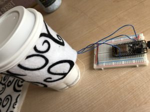
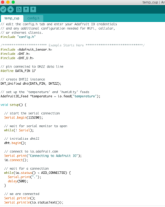
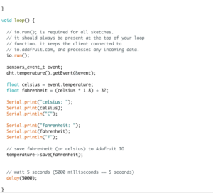
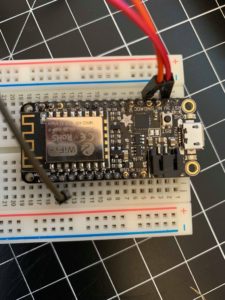
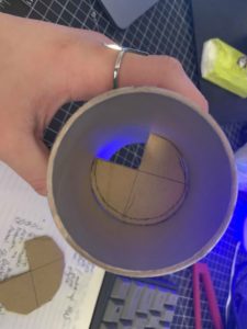
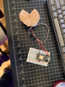
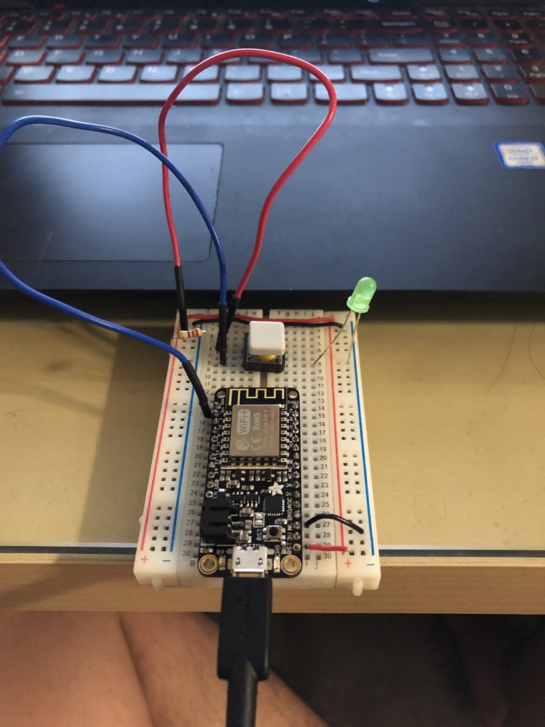
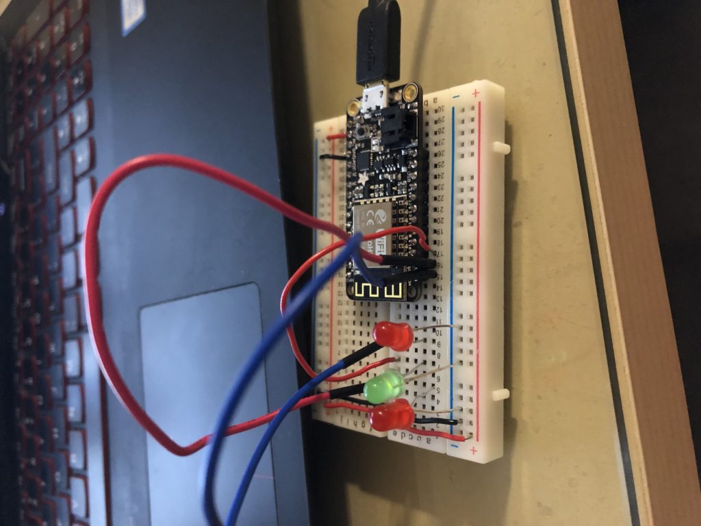
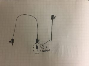
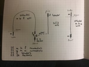
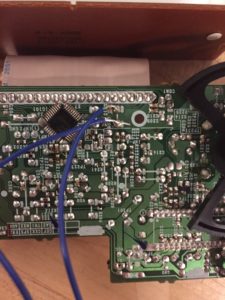
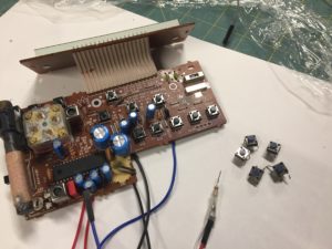
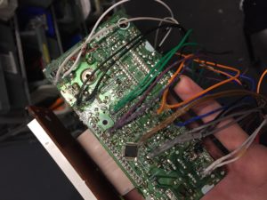
Building the hardware was probably the best part of this project for me. I enjoy taking an idea out of my head and turning it into something I can hold in my hands. I started by wiring up the OLED display to my microcontroller and running the Adafruit test sketch to make sure it all worked. Once that was all set up, I got to work disassembling the alarm clock and making a hole for the display to be visible through. This was a lot more difficult than I expected, as the clock face was about 4mm thick and made of very tough plastic. I ended up having to drill a few holes and then cut out the space between them with pliers before I could fit a file in there to get the hole to be the right size and shape. After that was done I made a power-distribution board out of a solder prototyping board to connect power and ground to the various parts. I used a DC-DC step-down converter to change the 3.3v from the microcontroller to the 1.5v the original clock movement and motor ran on, and I used a small transistor to switch the power going to the motor. Once all of that was wired up all that was left hardware-wise was to secure the screen with a bit of hot glue and close up the back, and then came the difficult part: getting the software to work.

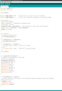
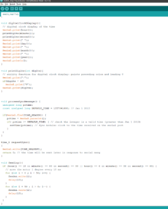
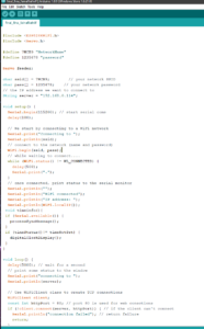
Dealing with time and time zones can be a bit of a headache, and I’ve never been a particularly skilled programmer, so I quickly decided that writing my own clock software completely from scratch was out of the question and went looking for an open-source implementation I could modify to suit my needs, and I found it here. It wasn’t exactly what I needed, but it made a good foundation to start with. The alarm function worked perfectly , but the display only sort of worked, you could kind of make out the time but it was formatted for a different aspect ratio display and it came out mostly garbled. It took a bit of digging through the Adafruit I2c OLED display library but I eventually figured out how to make it work and cleaned up the text, removing the date, day of week, and seconds to make room for a clearer, more easily readable time display to set the analog clock to. After that, I decided to add a few more buttons to the web interface, because the original one only had the option to increase or decrease the alarm one minute at a time, which was a nightmare to use on my slow, unreliable WiFi. I added +5 and +30 minute options and that streamlined things greatly.

My modified code can be found HERE

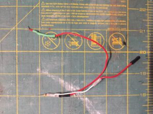
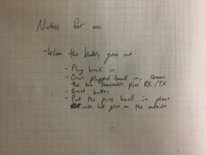
Overall, I’d consider this project a success. It sets the time automatically over NTP and it did manage to wake me up every morning I tested it on, though there are a few things I’d like to add. I want to re-implement the key switch function at some point so it really forces me out of bed, hopefully with a slightly higher quality switch this time around. I also figured out a really easy way to reverse the polarity on the battery connectors the ESP8266 Huzzah board uses, as the ones I bought came backwards. You just have to lift up a little plastic tab with an x-acto knife and pull each wire out. You can then pop them back in in the correct polarity for your microcontroller. The batteries I bought don’t have enough capacity to run the clock for more than a few hours, but they’d be enough for if the power went out for a couple of hours or if a cat, dog, or small human accidentally knocked out the USB power supply during the night.

Santarelli Final Project

Here’s my final project. I hooked up the adafruit neopixel lights to my share music graphics app that’s on the App Store. https://itunes.apple.com/us/app/share-music-graphics/id1446148157?mt=8   

The app would ping the Apple Music API for their colors that they associate most with the album cover, and then sets the background color of the app. As soon as the background color is set, then the app sends a post request to Adafruit Data Broker service creating a string of the background color’s RGB and then the Arduino would take that string and then parse it, turn it into and integer and then set the RGB values accordingly. It was a little tricky getting the Arduino with the string to do these which is why I had to add X’s into the string when a value was missing because of how strings are char [] arrays on the Arduino board. 

Here’s the link to the code that I wrote: https://gist.github.com/Alexs2424/f9ac29a5af45a0bb8a99bea4a9c9179b 

Here’s the swift version: https://gist.github.com/Alexs2424/d583552f8664c0d82d6932fe1df918e0

Then if you hit the change color button on the app like it is on the ui, whatever the background color is, it changes to the light strip. I really liked this because this was really interesting to do more of an installation piece, where the Arduino does something in real time. I loved figuring it out and seeing how fast the data broker can be sometimes, it’s super fast for all the multitude of services, requests, that the device goes through, it’s pretty mind-boggling that everything can work that fast. 

It didn’t work in class because two of the wires were confused and switched around, which was completely my fault. And to learn to have the demo hooked up before you go on stage, and also when you get it to work to take. Video of it. 

Here’s the link to a video of all of it going on, in the app and the lights changing in real-time.

https://youtu.be/9jGVdbKXK_o 

Final Project: Temp Cup

The basic idea of this project was to create a coffee cup handle that measures the temperature of the cup it is holding. But it evolved into a tracker of your drinks according to the temperature. The end up product looked like this:

The temperature sensor, the LM35 sensor, was sewed behind the felt cover on plain fabric and this fabric was sewn on to the black and white felt cover. The wires were soldered to the ports of the sensor because sewing it with the conductive wire fell apart. This then attaches to the microcontroller.

To set the reminders, the triggers were set up in the If This Then That app on my phone, and the two triggers looked like this:

For the monitor in Adafruit, I set up a temperature block that monitored the live temperature feed every time I am operating the microchip. For the code, I used a simple temperature measuring code from the library.

After setting up the Adafruit key and connecting it, I started running the programme before every time I got a hot or cold drink and my calendar sort of ended up looking like this.


This was only for a week, but if extended, this can go on for more time. One of the important problems associated with this was the fact that I had to switch it on before every time I got a drink. If there was any way of making it automatic, I would actually consider it as a viable product since I really do need to control my bubble tea and caffeine expenses. Sometimes, the sensor wouldn’t read the temperature properly, so I had to press it against the drink and then remove the cup sleeve after it read the value and switch it off so it didn’t take too many readings and add too many events to the calendar. Below are two example days which had a reminder on my phone. The shortest amount of time was a duration of five minutes, so that’s what I set it as.

Overall, I was pretty proud of this project because I knew exactly what needed to be done and how I had to do it for all the steps, unlike my midterm project which was a little more than I could handle. If I could, I would probably try and search for more ways to make this process more automatic, but I wasn’t sure how. That would give me a cup sleeve that thinks on its own, telling you when to stop slowing down on drinks, because you have spent way too much money on bubble tea!.

Final Project: Automatic Feeder

Throughout this project, there are a lot of things I learned. I learned a lot of new things about various hardware and even new things about programming. And as corny as it sounds I learned a few things about myself that I could improve on.

This project took many different turns and detours throughout these few weeks. After many trial and errors I finally the entire project to work. Working with the hardware was definitely easier than working with the programming side. I ran into a lot of problems with the programming aspect of this project. This is where I should have asked the professor for some help and advice for.  This is the aspect where I had to learn more about myself is the fact that I have to learn to ask for help. If I had asked for the professor’s help earlier I would have gotten this entire project down earlier.

With this,  I was able to get the automatic feeder to work! Unfortunately, through this method I am only able to get the feeder to work if I use the time library. I am able to use the code to start the internal clock at a certain time. This code uses the internal timer to set the servo motor to move at a certain time. I set it so it would be move at 9 A.M and 6 P.M. A normal time for a dog to eat.

For my set up, I had a cap on the top so I could put in feed through the top. For the bottom part I had two cardboard pieces cut out. Both of the pieces both had a 45 cut out of them. The bottom piece would always be stagnant so I had it hot glued to the container. Then the top piece would be the piece that was moving. I had the top piece connected to the servo motor so the feed would be able to go through the holes that were cut out when the two cardboard pieces would be aligned. I had the Servo in a sweeping motion because it is the most efficient way possible.

Finally, the final step for my project was to use the api into getting the webpage to work. Getting the api to work was not that hard due to the fact that the code was already on the class website. I just had to figure out how to use the code efficiently to make sure the servo would turn at the specific times.


Final Project Update: Programmable Pedal

Since last week, I’ve made a few changes to my project. I added the Max object “sm.ladder~” from the built-in Max package “smFilterPack” (you can find the package manager under File → Show Package Manager). The “sm.ladder~” package acts as a high pass, filtering out high frequencies to change the sound. This in combination with the “lores~” object (which changes the harmonic content) creates a more realistic simulation of a wah-wah guitar effect. I am still using the sewing pedal to control the effect.

I also created a simple visualizer in p5. The text moves up and down based on the volume of my guitar playing. This visualizer would be more useful if it could give information about what effect settings I’m using; for example, if it could display which effects are currently on and which ones are currently off, and the settings I have for each effect. This would create a cool graphic interface that would be easier to read than the Max patch. The image below is a good example of what I’m talking about. Unfortunately, I didn’t get that far, but it’s definitely something I want to explore. 

I did a short run through of the “wah-wah” effect and the visualizer in the video below.

Final Project: Silent Alert

The idea in mind that I had was for the ESP2688 to detect whomever came into my house. The sensor would pick up any movement that was near my door and would send an IFTTT message to my phone via Adafruit IO. The idea is that when someone comes through the door, and I was in my room, I would know if someone came in through the house via text message. (Sorry for the ugly look, didn’t have the resources to make a nice-looking case). To mount this near my front door, I had some adhesive 3M strips and a small battery to hook up the board to in order for it to have power.


When trying to develop the Wifi integration, I ran into a slew of issues. Firstly, I could connect everything together and make sure everything was working in terms of software. I could not figure out how to set the parameters of the Sensor feed from 0 to 1 since that would trigger the alert on my phone.

The main issue of the project was the PIR sensor itself. No matter what, I could not get it to be consistent with detecting movement. It can and has detected movement, but won’t do so accurately and coherently. On top of this, the only time I was able to get it to work is by re-uploading the code each time I saw that the serial monitor showed no signs of movement.

As you can see here, the sensor would rapidly detect movement. I thoughts at first it was the sensitivity of the sensors, but that was proven to be wrong as the Serial monitor would only sometimes show a rapid-fire of movement detection.

The code listed below was helped on by Dom and advice given from Professor Fitzgerald.

There was also another tab with an Adafruit IO key and username that I will not share for privacy sake.

Overall, I am disappointed that I wasn’t able to get this to work. I have about 3/4ths of the project complete. The only thing I need to finish up on is the integration between IO and IFTTT. For some reason, I can’t get IFTTT to work no matter what I do. I think better time management and preparation for this project would have put me in a much better position. I am glad to have gotten this far in my project, given how inexperienced I am with connecting devices via Wifi.

Final_emoji

For my final project, I create a physical emoji, which allows people to emoji react to jokes by physically squeezing it and making a squeaking sound. A joke will be shown on the screen, and people can squeeze the emoji to drop down and express their emotion to the joke.

In order to avoid the screen being filled up and the joke covered by the emojis, p5 will stop renewing data once the maximum receiving number is reached. Once the maximum is reached after 3 seconds, all emojis will bounce up and fall out from the screen. After all emojis have already left the screen, the joke will be renewed to the next one. The number of emojis will be reset to zero so people will be able to drop down new emojis again.

For connecting p5 and Arduino to make real-time interaction, I used Adafruit.io to send and renew input data.

At first, I was planning to create four different emojis (sad, curious, smile, angry) and each one has their specific way for interaction, such as squeezing for smile face (tilt or force sensor) or wiping tears for crying face (moisture sensor).  I end up with only two emojis, angry and smile, and both of them can be triggered by force sensors. I cut down to only two so people will be able to spend less time on deciding which emoji to drop and the interaction between two emoji can be noticed more obvious and easier.

In order to represent how people react to the counterpart in the real world, I made the smiley face scale down and change its color when there is an angry emoji shown around them. The majority always tend to use an aggressive way to change the minority’s opinion, and the minority will possibly start to be afraid and stop speaking out their voice without hesitation or fear. 

I decided to use dog squeak balls as my physical emoji’s main component so there will be a goofy squeak sound when people drop down an emoji. And I place them on a box which I laser cut with four holes on it, two for placing emoji and two for LED light. 

The difficulties I met through the process are mostly from p5. The most time I spent on this is making emoji automatically refresh after the maximum is reached and switch to the title after every emojis has already fallen out from the screen.

If I have more time on this project, I would like to refine the physical part. Probably make the emojis softer and redo the box with wood board or acrylic board instead of cardboard. I’d also like to think about how to make the p5 emoji interaction more visually exciting. 

Final Project (Final Update)

I tried to make an instrument tuner and display whether you were in tune with 3 leds. One green led would say you are good, 2 red leds would say that you are too high or too low. I tried to do communication from a p5 sketch to an arduino with OSC. I couldn’t get it to work though, so it is kind of unfortunate.

I tried to do serial communication at first but that didn’t work because it just doesn’t work well on Windows computers? So I switched to OSC, but I also had a lot of trouble with it. I can get a basic sketch to work which lights up an led according to where the mouse is. I’m kind of disappointed. I thought once I got a basic sketch down, I could apply it right away to my p5 sketch I already had, but it didn’t work out like that. I feel like it has to do something with the order setupOsc is in my setup function as well as where my sendOsc’s are in my draw function. I can get what I want to send in my console; I’m not sure what’s going wrong. It also doesn’t connect to node.js. I don’t know I stayed up and tried to make it work, but it just doesn’t. I feel like I was a bit too ambition, but also I feel like I could have gotten it done. I was just so busy this semester.

But I guess it can be like some kind of strobe light that goes off while I play the guitar. Just so it could be a little more flashy, than just seeing me play the guitar.

The thing is I really want to get this working, so I’m going to continue working on it. It seems like a waste just to stop here and give up.

UPDATE

So I tried to change the way my tuner would work. Since I was not getting the code to work the way I wanted to, I thought trying to make the p5js sketch only recognize one string frequency would be easier, but like before when I added osc into my sketch the sketch stopped working. It just didn’t work at all.

Instead of that I tried to make the arduino send a digital signal of a button over to a p5js through osc. When the button was pressed it would make the p5 sketch play the sound of a string, with which the use could use to tune their instrument by ear and also help them to gain better pitch detection. The led on my board was so that I could see that the button was actually working, when I was not looking at the serial monitor. I don’t know if it was the order of the code or something, but some things in my sketch wouldn’t load while others would depending on order. I know that my p5 sketches worked by itself because I demonstrated them in class but, when adding osc in it stopped working all together. All my code is here in my github. Even the ones that didn’t work. Below is the button I wired up to play the E string of a guitar. As you can see in my new video the p5js sketch connects and also receives the messages, but the sound just doesn’t play. 

I feel like I just made things harder for myself, instead of trying to think about what I could do. If I thought of easier ways to do this, I think I could have done the project better. I thought that once I could get serial communication done, everything would be smooth sailing especially since I had everything else done. But I just ran into troubles right when I started using serial communication. When I started using osc, I thought it would be easy to do everything especially since it was an easier to use, but again I ran into trouble.

This is my led layout for my tuner I wanted to make.

Radio Controller

Hello!

This is my final video showing the eleven working buttons:

And here are some images that document my development process:

some little drawings I made while first attempting to visualize the network inside of the radio:

once I generally figured out where things needed to be, I sketched out various components so that I could streamline them–this is the GND end of each button:

one of my first attempts at making a said GND component:

I then sketched out exactly what I would need to connect all eleven pins on the microcontroller to all eleven buttons on the motherboard. I later used this sketch to figure out what supplies I needed. I ended up not using the female headers because I could never get them to work quite as well as premade, already-connected female headers on m to f connectors–I often cut off the female ends of m to f connectors and used those instead:

I began prepping the inside of the radio and wanted to get as much room as possible, so I removed the radio’s glued-in speaker (among other things):

I then began experimenting with soldering onto the motherboard. I couldn’t figure out how to solder onto it well–in part because the solders in the Fab Lab suck, in part because I was using solder that was too thick–and Scott did this demonstration, which I then used as a model:

after soldering a few wires onto the motherboard, I realized that the preexisting buttons simply weren’t reliable, and especially weren’t reliable when multiple were connected to the same power and ground. so I went through and replaced the buttons with newer, more reliable ones.

after a lot of work, I figured out the interior logic of the motherboard and arranged all of my powers and grounds so that there would be no shorts. I color coded the buttons so that I could keep track of their wires and then hot glued all of the soldered connections to protect and strengthen them:

here’s my final master-key, although it’s probably pretty unintelligible. I used this to keep track of the radio’s external buttons and their respective 1) “button number” 2) wire color 3) pin on the microcontroller. I used the button number to organize the buttons in Unreal Engine. This was super necessary and helpful:

and here are some final notes that I needed to write down for when I come back to this controller and don’t understand why it isn’t working. It primarily has to do with the RX and TX pins:


All in all, I’m really happy with this controller. I’m also happy to say that my controller was actually fully functional when I displayed it in class–I’m pretty sure the clock wasn’t showing up because of how widgets are displayed in UE4 on differently sized windows, and the window size had changed when my computer went into projection mode, and I’m pretty sure that the bloom button wasn’t responding because I’d screwed the back of the radio on too tight and the button was being continuously pressed down. When I went back to my dorm and tried it, everything was working fine. I’m genuinely proud of this project, it’s actually really cool, and I honestly want to make it again except better, knowing what I now know.

Some potential improvements for a later version:

  • Using the other bits and nobs on the radio
  • Minimizing the amount of space taken up by wires
  • Finding a microcontroller with more normal digital in/out pins–the RX/TX pins aren’t sustainable for a final version of this project
  • Making it all fit nearly into the radio so that every button feels the same when pushed down
  • Figuring out a recharging system that doesn’t require me to open up the radio, but that is also still discreet enough to make the radio look and feel wireless
  • Cleaner, better planned out relationships between the buttons on the motherboard and the pins that they’re connected to