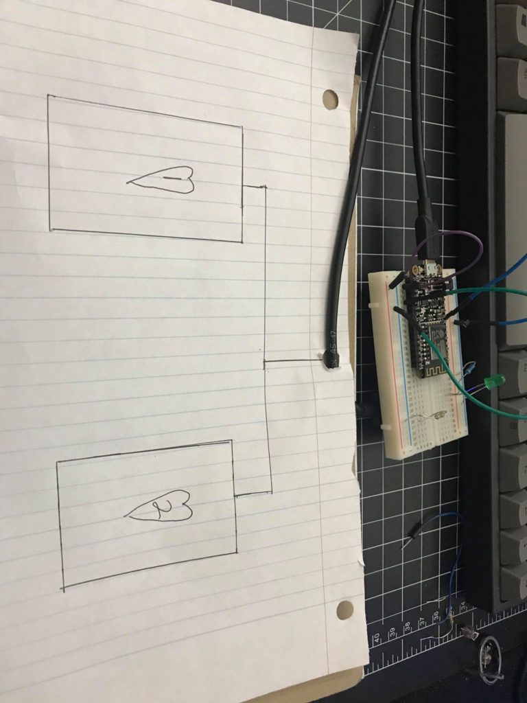
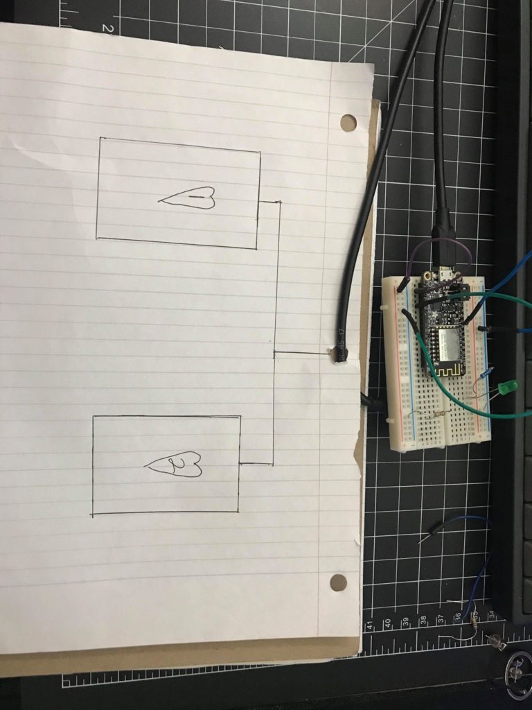
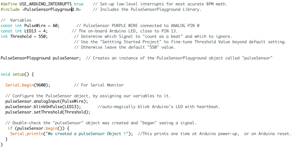
For this assignment I wanted to create a theoretical love machine that was attached to the breadboard. The reason I wanted to make it theoretical is due to the fact that “love” cannot be quantified. But in this “machine” I wanted to create two theoretical switches that could analyze someone’s personalities and match them with each other. And if the two personalities were compatible the LED on the breadboard would light up, signify that there is a sign of “love”
For my love test machine I decided to go with more of a classic interface. Those old machines usually take an input and don’t tell you how you did until the whole game is finished. My idea was to take a button, you press it once to start the game, once the game is started then you start tapping the button furiously as possible to see how many times you can get it to go.
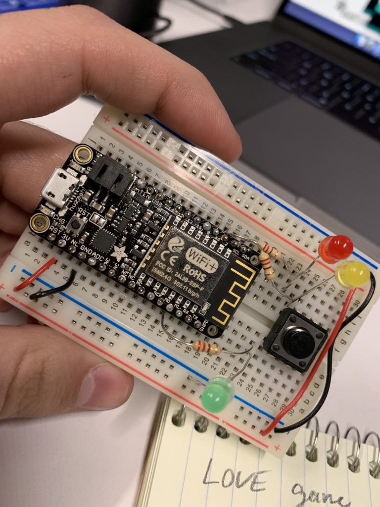
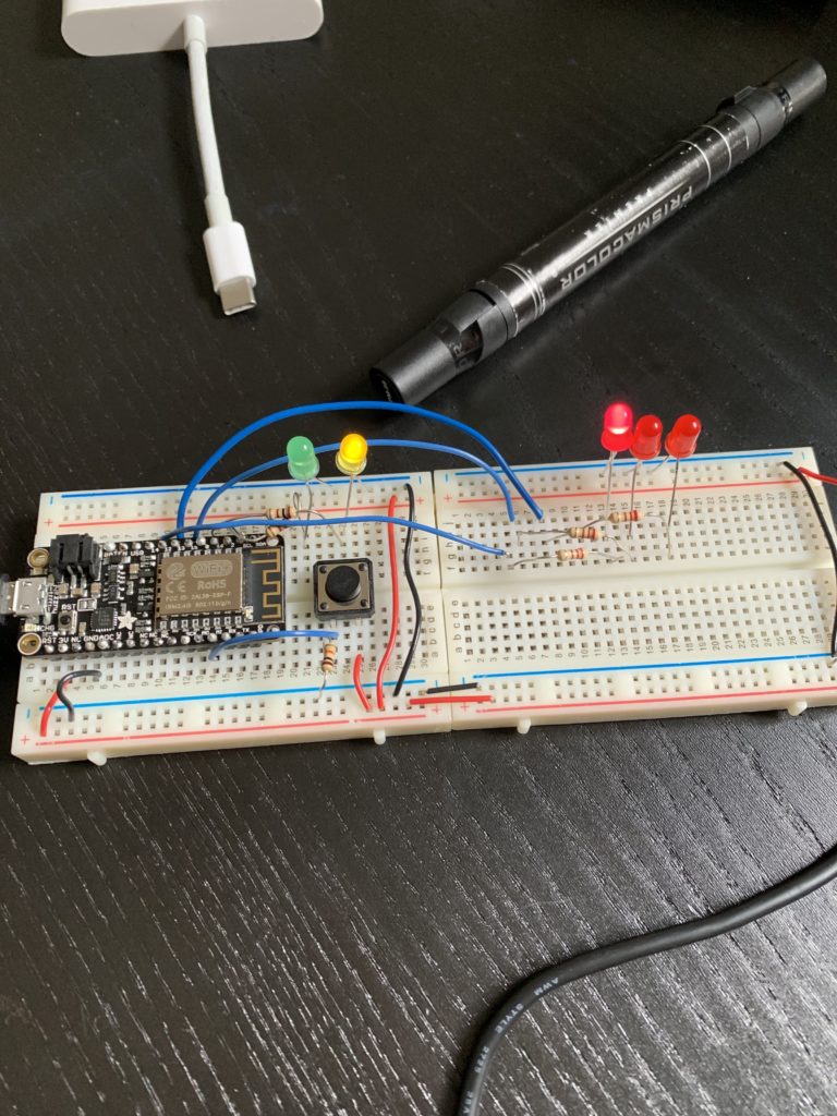
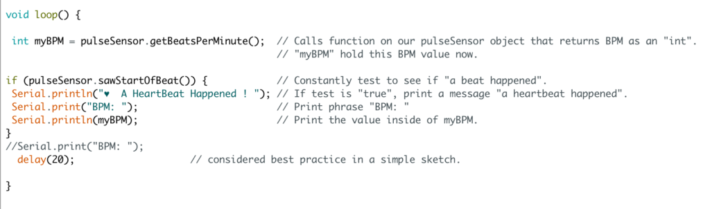
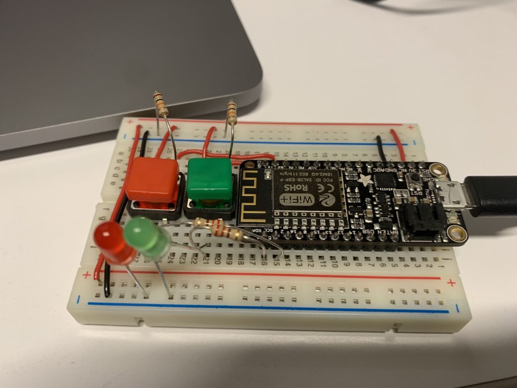
With the readings from last week, I understand that you have to make it clear to the person what they’re doing and where they’re at in the game. They also need a feedback mechanism so they know what’s going on. I used the lights on the left hand side of the board for that purpose. Yellow for when the game is about to start, Green for when the user should tapping as hard as possible, and the three red leds on the right hand side of the board indicate the results and how you did.
Because I was at first struggling with understanding, I started with writing the code for the leds, in order to sequence them in the way I wanted them to. Once I was able to do that then I added in the switch and once I turned the switch into an on and off sequence that’s when it really started to come together. I then organized the components onto another side of the board in order to make sure that it was understandable and doable.
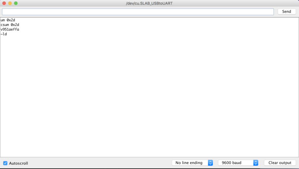
The one issue I have is in the middle when you’re tapping the button delay doesn’t work but I was wondering how I should go about letting the person tap as many times as possible before going onto the next step for like 5 seconds.
*my phone images can’t be uploaded because of HEIC
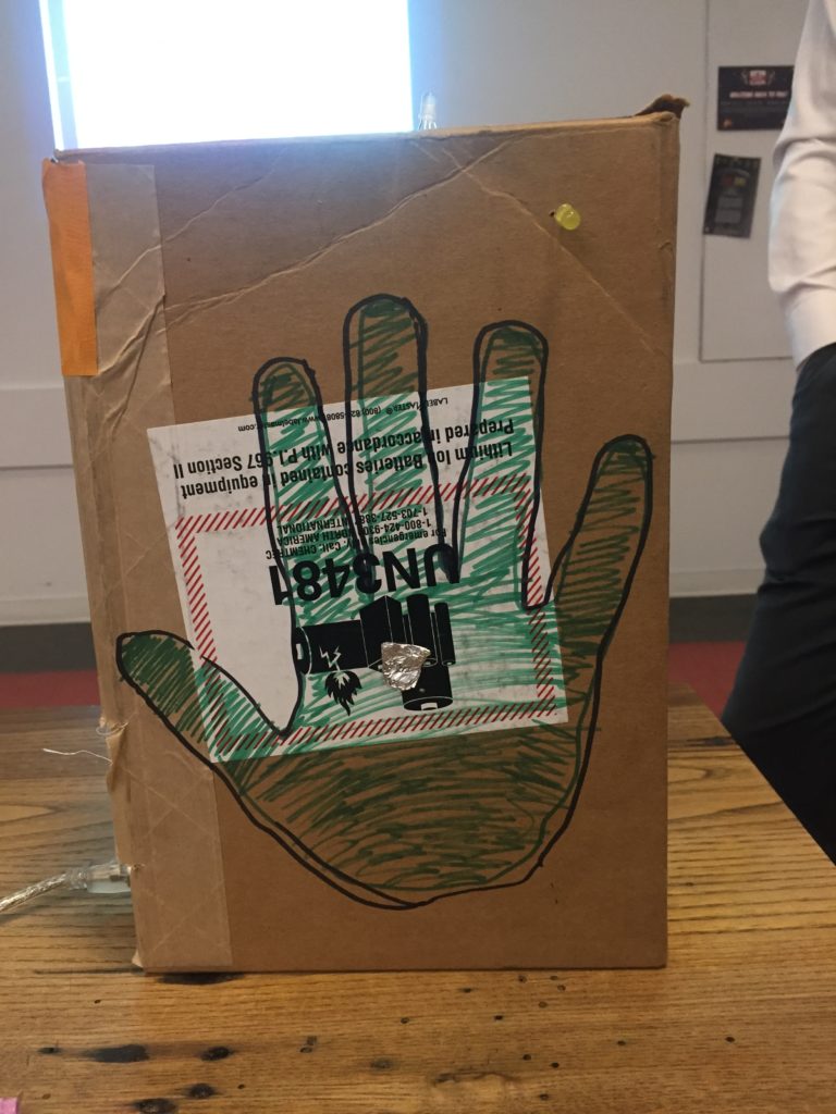
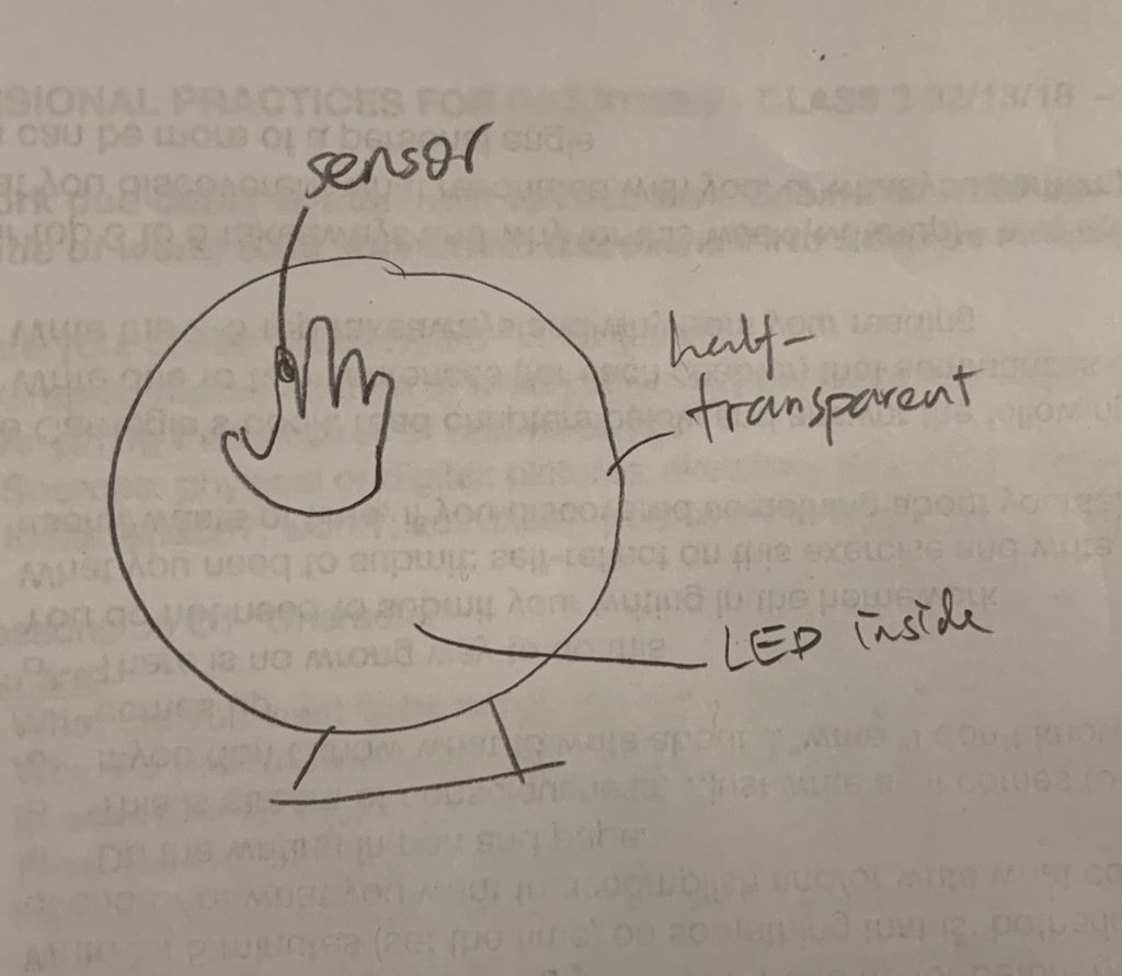
I felt inspired by hands after our hand free switches and decided to make a love machine that required the two potential lovers connect with their hands. I had trouble thinking of way to activate a switch upon their hands connecting so I instead used capacitive sensing to measure when the two people at placed their hand on the machine. Also in order to give the users some signifiers I added a hand-print outline to both sides and led’s that light when each individual hand is sensed.
Materials:
cardboard box (17 cm x 25 cm x 8 cm)
Arduino Uno
2 single-color LEDs
1 RGB LED
resistors (2 x 100K ohm, 5 x 220 ohm)
tin foil
wires
breadboard
Process:
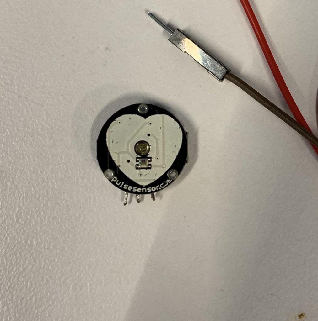
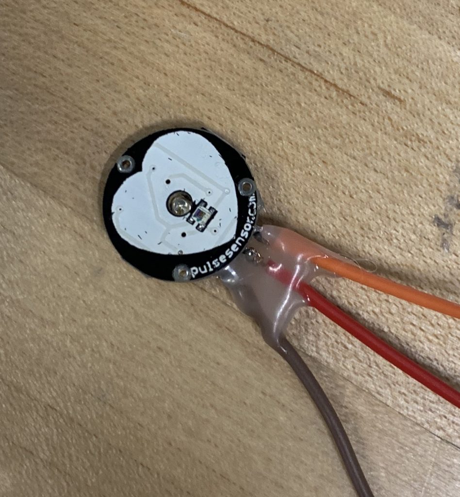
I started with getting the capacitive sensing to work. Essentially capacitive sensing allows us to read whether or not physical contact has been made to skin. It can even sense through other objects if a large enough resistor is used. I used the Arduino CapacitiveSensing library. This is the circuit diagram provided in the library’s documentation:
Capacitive Sensing Circuit
Essentially two digital pins are needed to use capacitive sensing, but one send pin can be used for multiple receive pins. Also the resistor needs to be at least 10k ohms but ideally between 100K ohms and 50M ohms. The larger the resistance the more sensitive the sensing is. I also linked two LEDs to capacitive sensor to give a visual indication if they were being sensed. Sometimes one needs to make firm contact in order for the signal to be picked up.
The next thing I needed to wire up is the RGB led. It is pretty easy to do, just need three pins to control each of the Red, Green, and Blue LEDs as well as resistors between the anode and digital pin. And one final pin that goes to ground. Here is the circuit diagram for that:
RGB LED wiring
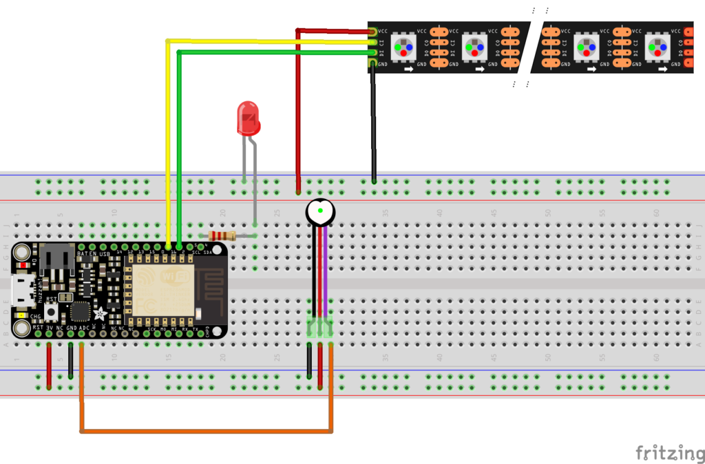
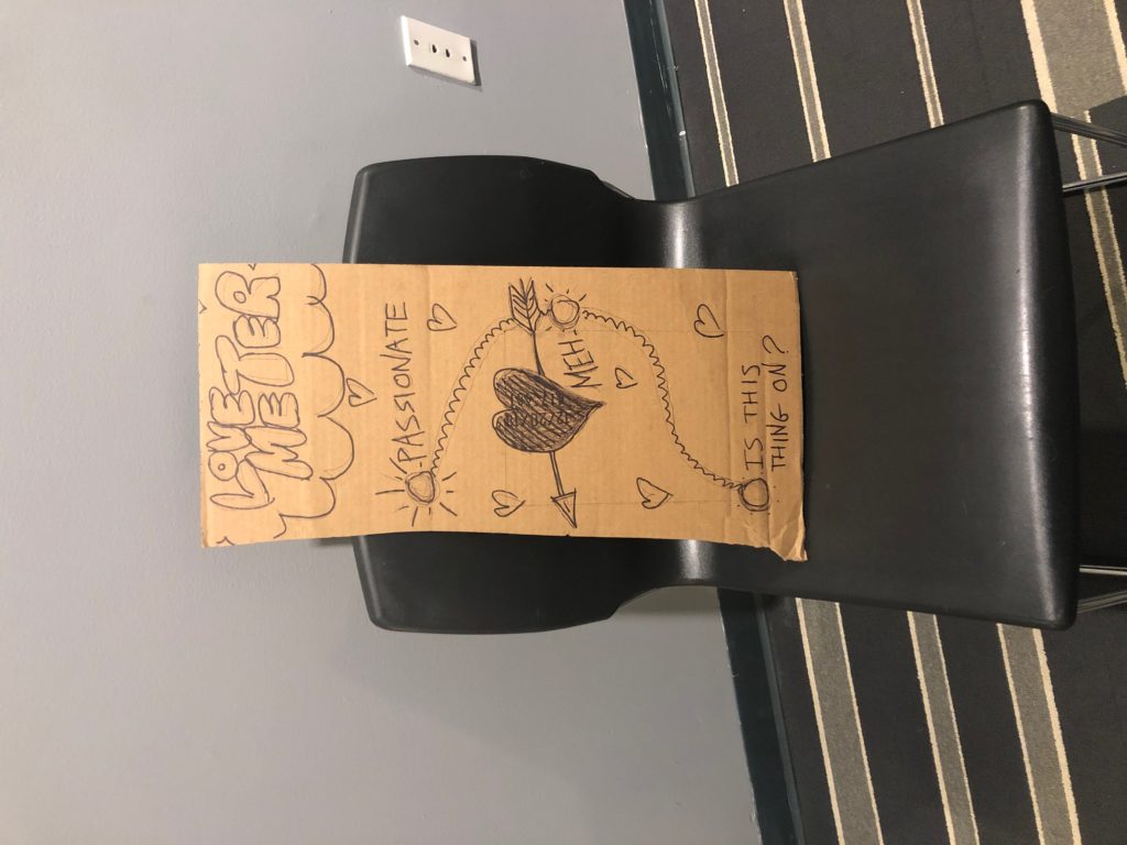
The final thing was putting all the components into the box. I poked holes for all the LED wires and just stuck wires out to connect to the palm of each hand. I designed it so that when the two users put their hands up it seems like they are putting their hands up against each others. I also made both hand prints right hands so that it was clear the machine is supposed to be used with two people instead of just one.
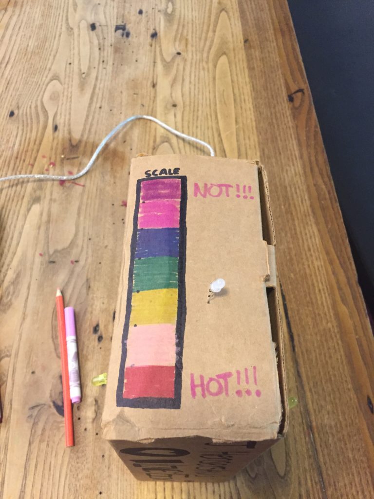
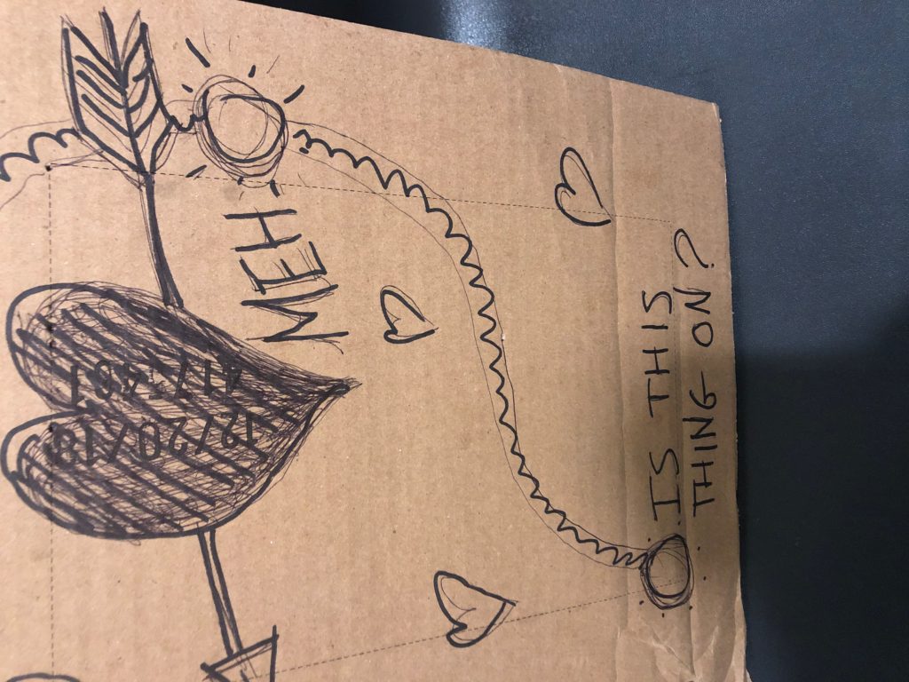
The LED stops on one of the 7 colors of the rainbow which indicates how good they would be together. Red being the best, violet the worst. I made a color coded scale on the top next to the RGB led in order to illustrate this.
The box is relatively self contained so there aren’t too many affordances here for the user. The only real option is place your hand where the hand print is. Once you place your hand an LED will light up giving indication that something had been activated. If they take their hand away the LED deactivates and its clear what caused it. When both hands are put up both LED’s start blinking rapidly and then stop at which point the RGB led cycles through colors until it finally picks one and blinks that color. A relatively simple yet self-explanatory device.
// Choose the colours to increment and decrement.
for (int decColour = 0; decColour < 3; decColour += 1) {
int incColour = decColour == 2 ? 0 : decColour + 1;
// cross-fade the two colours.
for(int i = 0; i < 255; i += 1) {
  rgbColour[decColour] -= 1;
  rgbColour[incColour] += 1;

  setColor(rgbColour[0], rgbColour[1], rgbColour[2]);
  delay(5);
}
}
}
void setup()
{
cs_2_3.set_CS_AutocaL_Millis(0xFFFFFFFF); // turn off autocalibrate on channel 1 – just as an example
Serial.begin(9600);
pinMode(led1, OUTPUT);
pinMode(led2, OUTPUT);
pinMode(rPin, OUTPUT);
pinMode(gPin, OUTPUT);
pinMode(bPin, OUTPUT);
}
void loop()
{
long start = millis();
long total1 = cs_2_3.capacitiveSensor(30);
long total2 = cs_2_4.capacitiveSensor(30);
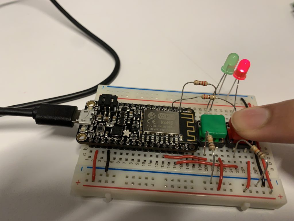
For my love machine, I wanted to emulate the swiping mechanic from dating apps into a button system. I wanted a way of matching people by accepting or rejecting them using green and red switches and LEDs. I programmed the microcontroller with two colored switches that are connected to their respective color of LED. If you press the green button, then the green LED would turn on. If you press the red button, the red LED will turn on. Instead of using simple switches, I opted to use the colored one so anyone using the circuit would know which button to use in order to activate the correct LED. This idea came from the Prepared Brain idea from “Attractive Things Work Better” where the brain naturally assoicates things such as color.
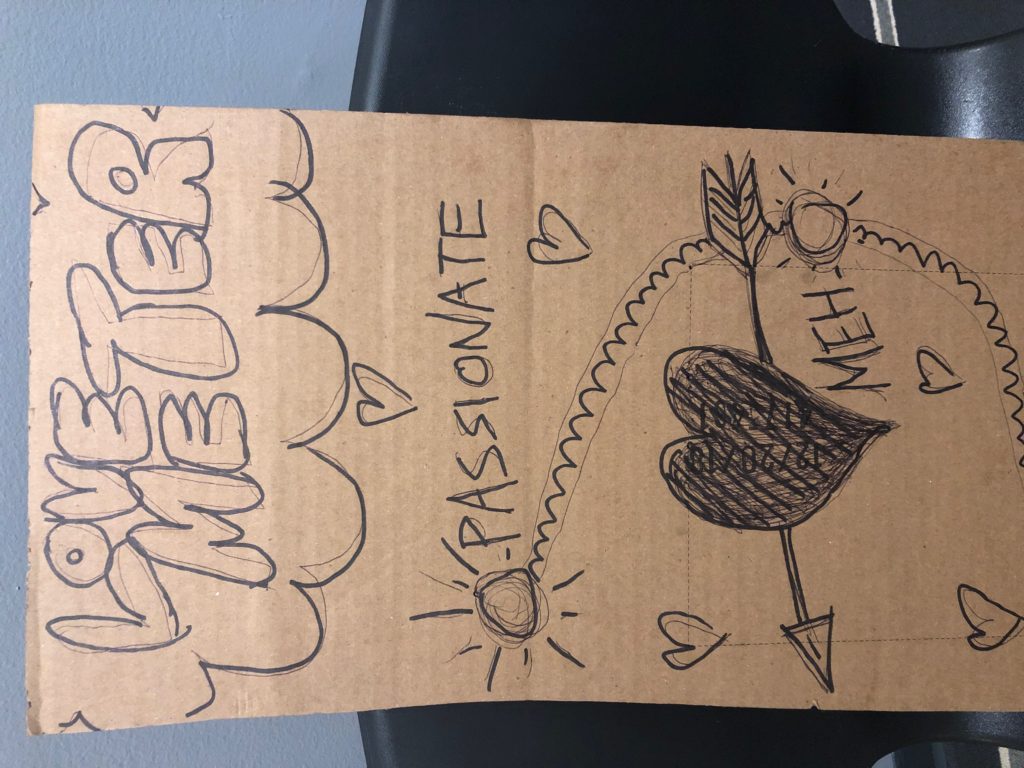
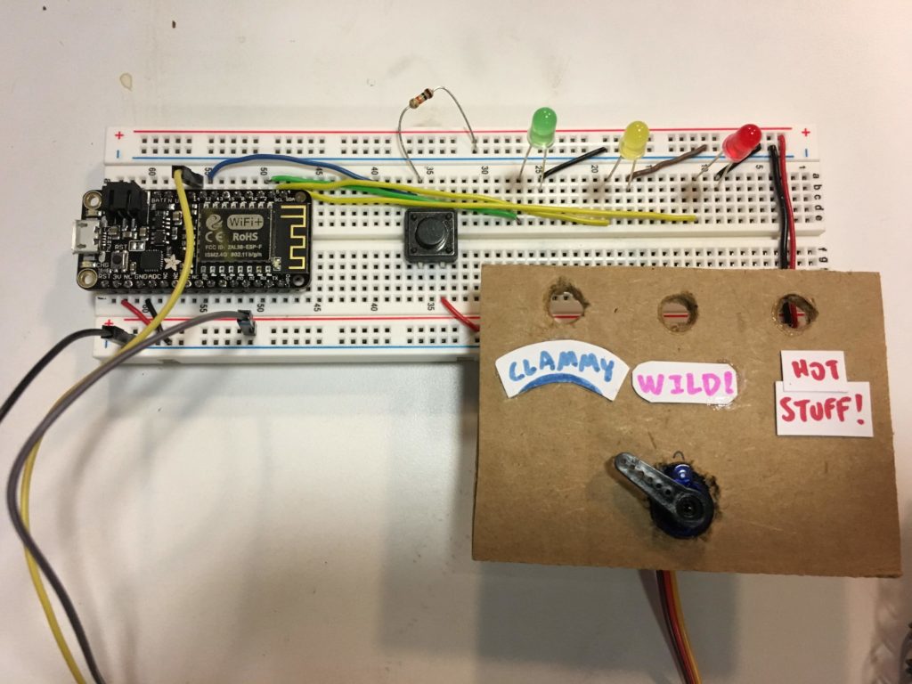
Initally, I created my love tester machine with a push button switch as the input, and 3 LEDs and a servo motor as the outputs. When the switch is pushed, the LEDs start blinking erratically while the servo sweeps back and forth, as the machine “decides” the compatibility of the couple. After a few seconds, it settles on an option by swinging its arm in that direction, while the corresponding LED lights up.
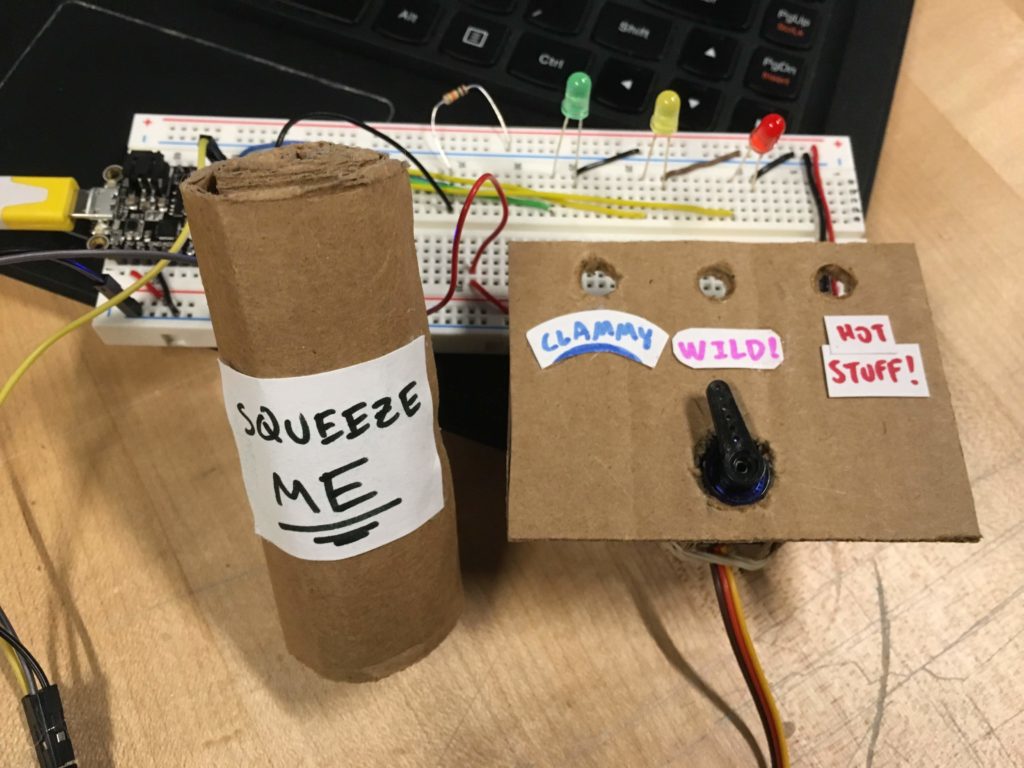
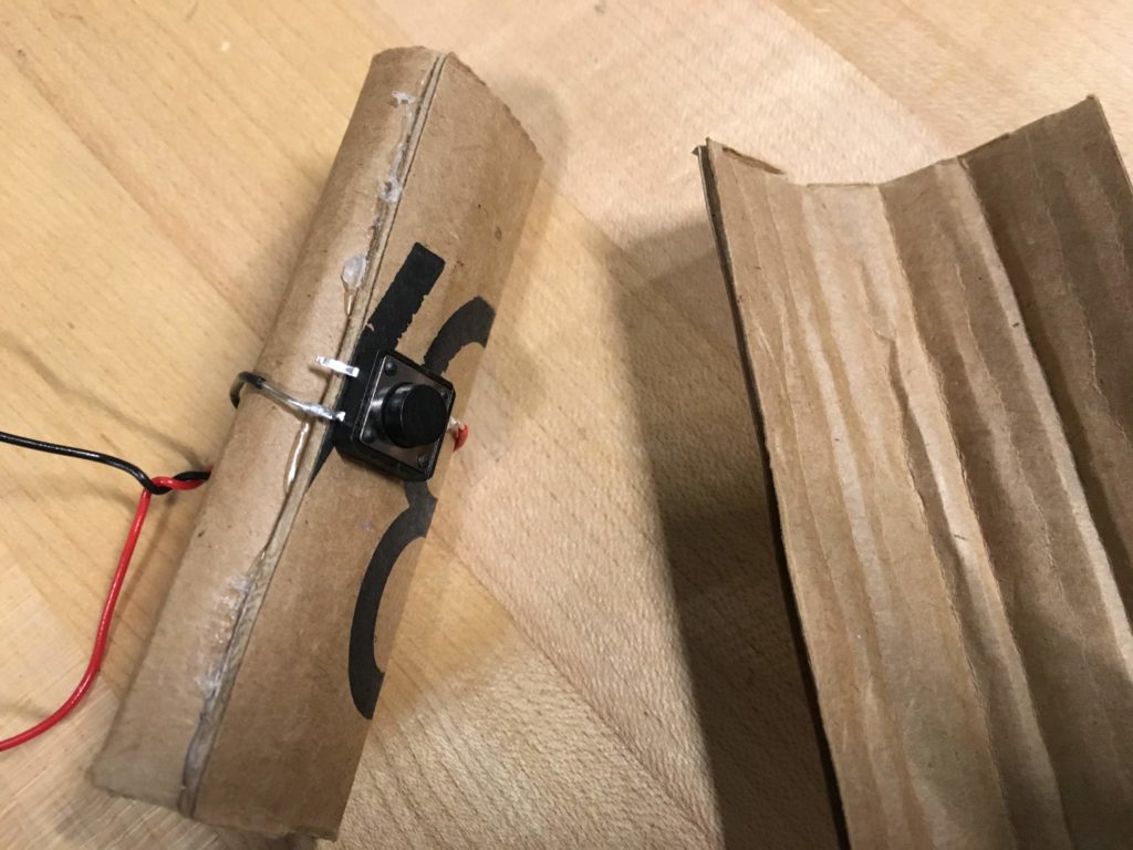
After thinking about the readings over the past couple weeks, I decided to iterate on my design. I thought about the Future of Interactive Design Rant, and noticed that the push button didn’t really utilize the full capabilities of our hands. So, I put the button inside a joystick-like thing so that when it’s squeezed, the button is still pushed in the same way, but gives a more interactive feeling to the user since their hands are used in a more natural way.
In this particular design, I think the joystick affords holding or squeezing with the hands, but since it wasn’t too clear, I put a signifier in the form of a sign that says “squeeze me.” This fulfills the role of a signifier by making the affordance of squeezing clearer. I also thought about the information taken in by the user and the information that is sent out by the machine. The tactile input alone has a bandwidth of a million bit/s; the LEDs that light up give out 10,000 bit/s and the sound of the servo turning gives out 100,000 bit/s. And although, consciously we can only perceive a small amount of this information, it’s interesting to see how it flows throughout the system.