Facial Recognition Switch

I ordered my components for class, but unfortunately I do not have any wires or other equipment lying around my apartment, and, living north of the Washington Square campus, I couldn’t find time between work and school to make the trip down to Tandon to get components to make an electrical switch. Instead, I offer up a slightly different answer to the assignment: a story of a handless “switch” hack in the form of a facial-recognition device I made a while ago.


This story requires some background: I was in a Stern class being taught by a professor who was a notable VC in tech. Now in that class, we were required to make ourselves name tags (as the class was 50+ people). Most students made simple little name tags of the paper-tent type. But, wanting to impress this professor with the hopes of either funding for whatever startup idea I was occupied with at the moment or a job at his company, I decided to get creative.

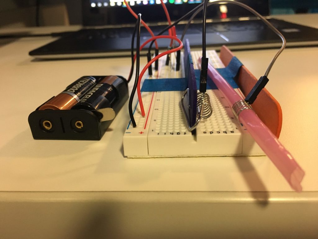
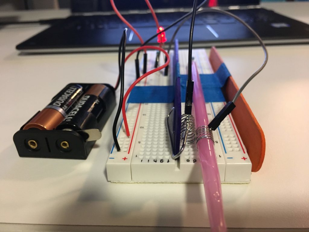
The concept was simple: equip a Raspberry Pi with a camera, that would recognize faces and print out a name tag (with a photo, full name, and title) for everyone it saw. The execution was a little more tricky. 
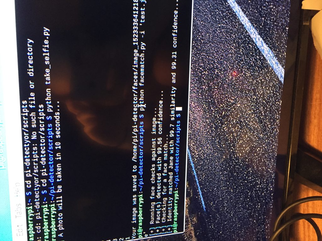
Getting the facial recognition program to run on the Pi wasn’t altogether too difficult. The actual facial recognition component I used was AWS’s Rekognition, which is astoundingly good. After that, a project I found on Github mostly got my Pi’s camera and Rekognition talking to one another without me having to do much work there. I trained my network to recognize photos of myself, my professor, and the handful of students that sat around me in class, and tagged these photos with details like their names. My Pi recognized faces really well at this point, so it was time for the printing component. 

The cheapest, most compact printer I could find on Amazon was a handheld Chinese point-of-sale receipt printer. This “POS” was truly a piece of shit, and I spent most of my time getting this little guy to work. This cheap and shitty thing required it’s own fucking driver (in the form of a mini-Compact Disk!) to be able to accept my Raspberry Pi’s input. Not having a CD reader in my apartment, I hoofed it down to the Staples off of Union Square that’s open 24 hours at 12:30am to buy one. This printer was also limited to printing only ASCII characters, so I had to convert my images to ASCII art.

An all-nighter later, the POS <-> Pi communication bugs were mostly solved, and I managed to get my little gadget working remarkably well!


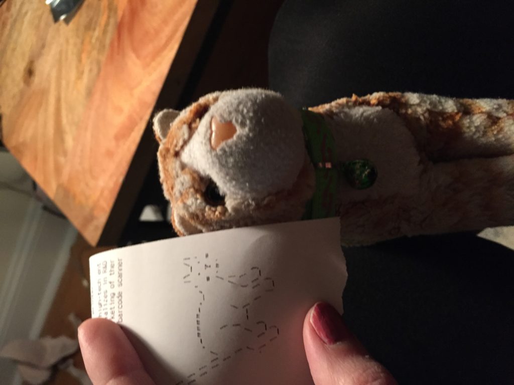
 I even managed to get it working on non-human faces, like this stuffed-animal cat I have.

For the purposes of this class, I don’t have a working model of this anymore (was cannibalized for parts soon after demoing it), and my documentation isn’t the most comprehensive. But I did get a job as a developer at my professor’s because of that build, so I’ll let that speak for its quality. And it was a fully-handless “switch” – it wouldn’t be hard to mount the Pi & camera on a door and have it operate a servo motor, effetely becoming a facial-recognition lock.

(Nowdays, I’m a little more swanky in the facial-recognition department and own an AWS DeepLens, which lets me directly hook up to AWS’s crazy amount incredible IoT offerings. Hoping to get to use this in class a bit in the future!)

HW1_Switch

For my switch project, I design a little punching machine. Unfortunately, you still need to use your finger to control it, but the way you trigger it is definitely more intriguing than just press the original switch button. As you might have already noticed, there is a seesaw at the bottom. In order to trigger the switch, all you have to do is try to shoot the disk, rolling in the middle, to the top and be attached by the magnet. For the conductive method, I have use aluminum foil, paper clip, and also some conductible wire.  It might seems difficult to reach the top at once, but practice makes perfect. However, this also makes the switch not convenient enough to be used. So my next step would be thinking about how to make the chance of hitting and attaching at the top more easily. 

(Update Feb. 28th)

Forward lumbar stretch switch

I spend far too much time on the computer, and in recognition of this fact I decided to make a switch that would prompt me to do some much needed back stretching.

For this chiropractic exercise I used my New York baseball cap, copper tape, an orange that my roommate gave me, a quarter, and an old piece of string.

The plan was this: I’d use some copper tape on an orange sitting firmly on the floor. Then I’d tape a long piece of string to the brim of my hat, measure the amount of string necessary to just reach the orange while in a full forward lumbar stretch, cut the string at that point, and finally attach a quarter to that string’s loose end using copper tape. I did all of that, and it turned out just fine. I plan on connecting the two conductors to an LED setup in class tomorrow.

In the ideal scenario, I would’ve simply stuck a quarter into the orange to use as a conductor, but I only had one quarter and I preferred that quarter be used to stabilize the string. In the end, I’m kind of glad that I only had one quarter, as the orange would’ve otherwise spoiled overnight, and I’d still prefer to eventually eat the orange so that it doesn’t go to waste.

In the doubly ideal scenario, I would’ve had a battery to use and wires to connect to a breadboard and LED light. Nevertheless, I got a good back stretch in, and so, in the end, I feel younger and more flexible than ever before.

Hands Free Switch

I started by envisioning some problems you’d run into if you didn’t have use of your arms. The thought of opening a door I believe would be a big hindrance and something that’d be really difficult. I wanted to make a better version of the handicap switches we normally put on the doors for people to open.

I designed it to have a longer area to be tapped in and the connection would be made at the bottom signifying something hitting all the way. This could be easily achieved by simply pressing any force into the top triggering a response when the circuit is completed to open the door. It would be something you could keep at foot level because I think that would prove to be a lot more useful and accessible. If you’re in a chair it can tap into it, if you don’t have full use of your arms you can use your leg to press the switch open, and even if you have your hands full.

Where are the clocks?!

Earlier tonight, I came up with the idea of lighting an LED whenever the hour and minute hands of an analog clock meet– this could be an unconventional way to tell time. I dropped by Staples, excited to get my hands on a clock to break apart! I was redirected to cvs, “they should have it.” Moments later…

“Excuse me, where can I find clocks?”

“Socks?” asked the lady behind the counter. 

To her co-worker: “Yo, where are our socks?”

Co-worker points vaguely towards ???

“That aisle, miss”

“Oh, I meant CLOCKS” ?

“Socks?”

Co-worker: “Clocks, the ones that tell time! Do we have clocks?!”

I left cvs with a roll of aluminum foil and proceeded to work on a new plan: to roll a wheel along a path so that when the foiled surface on the wheel gets in contact with the strip of aluminum foil at the end of the path, the circuit is “switched on” (aka closed). The LED could be “switched off” by rolling the wheel backwards (aka tilting the path the opposite way).

Having an open path was too risky. Can I make sure that the wheel doesn’t roll off it? I decided to set a fixed path for the wheel.

It just so happened that the box I cut this piece from had small slits on it. I took advantage of the slit and began thinking of how I could attach the wire to it without causing a bump in the path.

A perfect fit!

But attaching the wire to the path foil through this slit did not only cause a bump on the path, the tape covered too much conductible area.

🙁

I stuck the wire end to the foil strip in every direction but none of them seemed to work smoothly so I cut a wider hole for the wire to move through and eventually found that I could attach a wire end to the wheel’s foil strip through this hole!

Wheel and path not in contact
Roll it forward = contact!

The last piece of the puzzle was affixing the other wire end to the path’s foil strip.


After multiple attempts, I arrived at this setup. It works but I think there still could be a better way to arrange this. ??‍♀️

Hands Free Switch

I made a switch that resembles somewhat of a foot pedal. I tried to cut a box to make it more square like, but I didn’t have tape nor glue so I was left with this. I used copper tape that Professor Fitzgerald gave me to create a conductive surface. I put this on two sides of the cardboard. This would eventually touch when you put your foot on it and complete the circuit. The wires are aluminum foil wrapped up and these would attach to a battery.

This is my updated version. I added a led, but as it says in my comment. It didn’t work. And also my usb is janky so it doesn’t work; I didn’t have time to go buy a new one, so it was actually such an unfortunate week.

Hands-free switch

For this assignment, I decided to make a switch with uses your body to close a circuit. The circuit consists of an LED, with two transistors, and a power source. The LED’s power comes from two transistors which are only connected to the power source when the circuit is complete using your body as your body acts like a wire between them.

I demonstrated with my arm, but it could be done with any part of the body.

Below is the website I used to make the circuit:

http://www.mallinson-electrical.com/touch-switch-circuit

Update: This week, I tried to make my switch using the microcontroller. I couldn’t get the circuit to work with the two transistors or using the body as the conductor so I opted to use salt water as my switch.

The salt water was able to complete the circuit and act as a switch for it. I decided to implement the salt water as it was recommended by the link I used above for last week’s circuit.

Hands Free Switch | jh5363

When deciding what I wanted to make I thought that if I weren’t going to be using my hands for a switch, I would probably want to use my feet. Other parts of my body could be used but that seemed less convenient. Behold the foot switch!:

foot switch

It is essentially just two pieces of cardboard stapled together. The top piece has a cut out of a shoe and the bottom piece has four wires stapled on. These wires may need to be taped though for better stability. Behold the magic shoe!:

magic shoe

Its got tin foil taped on the bottom of the heel and the toe. This way the top two wires in the switch will connect and the bottom two wires will connect. This could either be used as two separate switches or it could be used to as a switch in series to make sure the whole foot is planted on the switch.

Pressure Pad Switch

For my switch project, I decided to make a little pressure-sensitive pad that completes a circuit when pressed, squeezed, or stepped on. I was inspired by a book of science projects I read as a kid, which featured a similar sort of pressure pad switch made out of double sided foam tape and aluminum foil. I didn’t have any double-sided tape so I had to improvise with what I could find. I settled on a sandwich of two sheets of copper foil with a square of thick packaging foam with a hole cut in it, then wrapped the copper-foam sandwich in blue tape to hold everything together. There are a bunch of different ways to use this switch, like putting it in a chair to turn something on when you sit down, using it in front of a door to tell when someone’s there, as a compact foot switch, or as a part of a custom game controller. You could also put it in your mouth and use it as a control input by biting down on it, but I wouldn’t recommend that for many different reasons.

Update: I tested the switch with my microcontroller and it works. I reprogrammed the microcontroller so it works like a toggle switch, which is probably how you’d use it if you needed it as a lightswitch

Hands-free switch

For the switch project this week, I created a circuit that is controlled with your mouth. The switch is mainly made up of two parts – a straw and a craft stick. Both of these parts have springs that are connected to wires, which are part of the LED circuit powered by 2 AA batteries. When the two springs touch, they complete the circuit and the LED turns on. The user controls the switch by blowing air on the straw, which pivots around a resistor perpendicular to the straw. As the straw rotates, the spring on the end touches the spring on the craft stick, which sets the switch to ON and completes the circuit. The straw can be blown back the other way to set the switch to OFF.

Switch in the OFF position
Switch in the ON position
LED on and the straw’s pivot function